Toshiba Portege M780 PPM78C-005006 Users Manual Canada; English - Page 83
notches on the computer and place the keyboard down.
 |
View all Toshiba Portege M780 PPM78C-005006 manuals
Add to My Manuals
Save this manual to your list of manuals |
Page 83 highlights
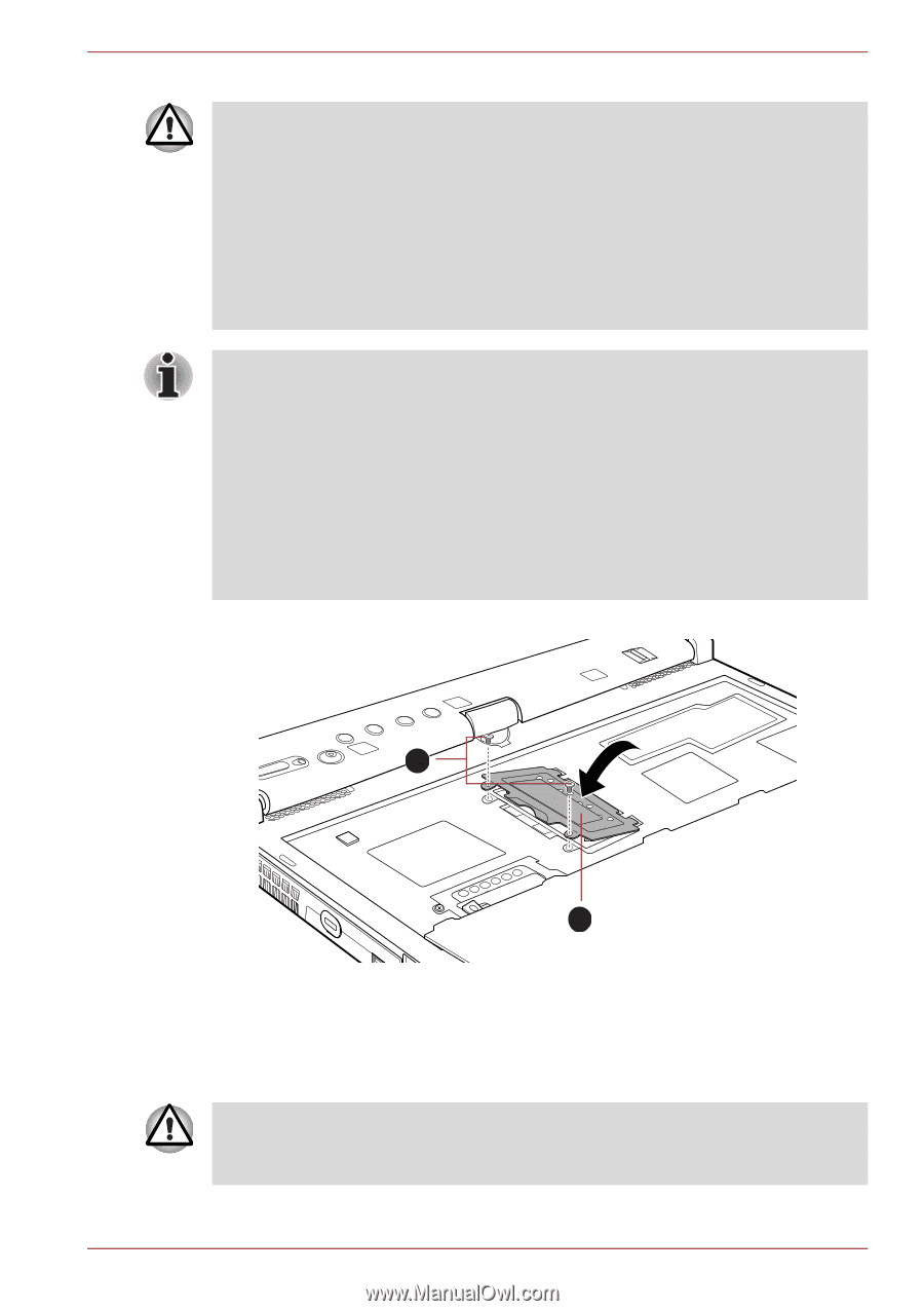
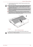
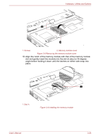
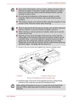
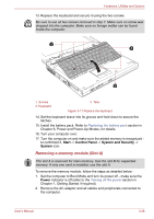
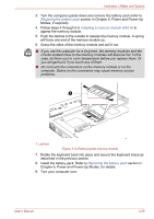
Hardware, Utilities and Options ■ Never allow metal objects, such as screws, staples and paper clips, to enter the computer or keyboard. Foreign metal objects can create a short circuit, which can cause computer damage and fire, possibly resulting in serious injury. ■ Do not touch the connectors on the memory module or on the computer. Debris on the connectors may cause memory access problems. ■ The memory module cover will be hot after using the computer for long periods of time. Exercise caution when removing. ■ Slot A is reserved for the first memory module. Use slot B for expansion memory modules. If only one module is installed, use slot A. ■ When inserting or removing memory modules, make sure to use the correct slot (A or B). ■ Align the grooves along the edges of the memory module with the locking tabs on the connector and insert the memory module into the connector firmly - if you find it difficult to install the memory module, gently prise the locking tabs outwards using the tip of your finger. Please also ensure that you hold the memory module along its left and right hand edges - the edges with the grooves in. 11. Screw in the two screws and replace the memory module cover. 1 2 1. Screws 2. Memory module cover Figure 3-10 Seating the memory module cover 12. Insert the tabs on the front of the keyboard into the corresponding notches on the computer and place the keyboard down. When seating the keyboard, be sure to connect the circuit board if the keyboard ribbon cable was pulled out while you were removing the keyboard. User's Manual 3-27
-
 1
1 -
2
-
3
-
4
-
5
-
6
-
7
-
8
-
9
-
10
-
11
-
12
-
13
-
14
-
15
-
16
-
17
-
18
-
19
-
20
-
21
-
22
-
23
-
24
-
25
-
26
-
27
-
28
-
29
-
30
-
31
-
32
-
33
-
34
-
35
-
36
-
37
-
38
-
39
-
40
-
41
-
42
-
43
-
44
-
45
-
46
-
47
-
48
-
49
-
50
-
51
-
52
-
53
-
54
-
55
-
56
-
57
-
58
-
59
-
60
-
61
-
62
-
63
-
64
-
65
-
66
-
67
-
68
-
69
-
70
-
71
-
72
-
73
-
74
-
75
-
76
-
77
-
 78
78 -
 79
79 -
 80
80 -
 81
81 -
 82
82 -
 83
83 -
 84
84 -
 85
85 -
 86
86 -
 87
87 -
 88
88 -
89
-
90
-
91
-
92
-
93
-
94
-
95
-
96
-
97
-
98
-
99
-
100
-
101
-
102
-
103
-
104
-
105
-
106
-
107
-
108
-
109
-
110
-
111
-
112
-
113
-
114
-
115
-
116
-
117
-
118
-
119
-
120
-
121
-
122
-
123
-
124
-
125
-
126
-
127
-
128
-
129
-
130
-
131
-
132
-
133
-
134
-
135
-
136
-
137
-
138
-
139
-
140
-
141
-
142
-
143
-
144
-
145
-
146
-
147
-
148
-
149
-
150
-
151
-
152
-
153
-
154
-
155
-
156
-
157
-
158
-
159
-
160
-
161
-
162
-
163
-
164
-
165
-
166
-
167
-
168
-
169
-
170
-
171
-
172
-
173
-
174
-
175
-
176
-
177
-
178
-
179
-
180
-
181
-
182
-
183
-
184
-
185
-
186
-
187
-
188
-
189
-
190
-
191
-
192
-
193
-
194
-
195
-
196
-
197
-
198
-
199
-
200
-
201
-
202
-
203
-
204
-
205
-
206
-
207
-
208
-
209
-
210
-
211
-
212
-
213
-
214
-
215
-
216
-
217
-
218
-
219
-
220
-
221
-
222
-
223
-
224
-
225
-
226
-
227
-
228
-
229
-
230
-
231
-
232
-
233
-
234
-
235
-
236
-
237
-
238
-
239
-
240
-
241
-
242
-
243
-
244
-
245
-
246
-
247
-
248
-
249
-
250
-
251
-
252
-
253
-
254
-
255
-
256
-
257
-
258
-
259
-
260
-
261
-
262
-
263
-
264
-
265
-
266
-
267
-
268
 |
 |