Toshiba Qosmio G40 PQG40C-MM108C Users Manual Canada; English - Page 49
Left side, Display latch
 |
View all Toshiba Qosmio G40 PQG40C-MM108C manuals
Add to My Manuals
Save this manual to your list of manuals |
Page 49 highlights
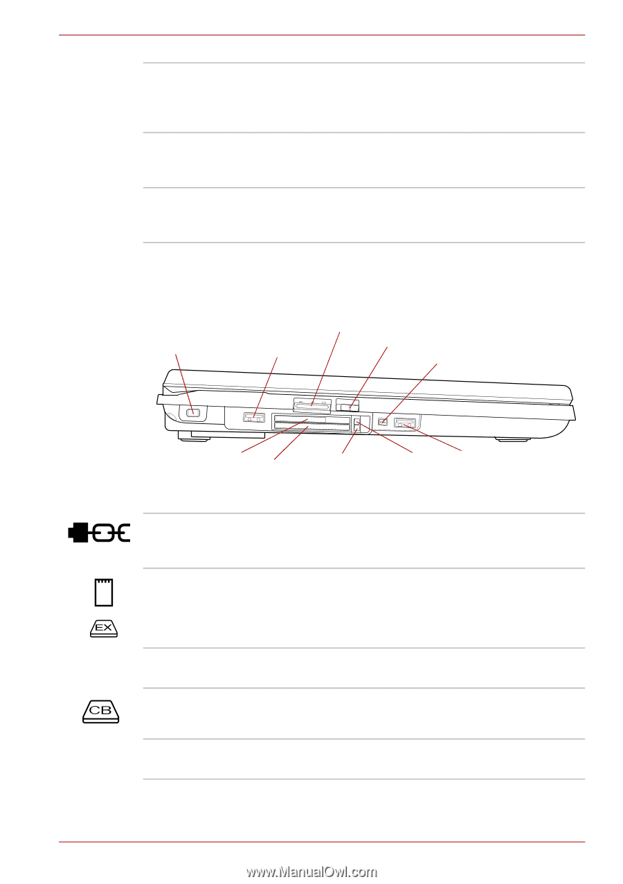
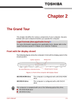
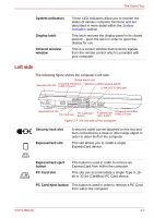
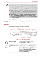
The Grand Tour System indicators Display latch Infrared receiver window These LED indicators allow you to monitor the status of various computer functions and are described in more detail within the System indicators section. This latch secures the display panel in its closed position - push the latch in order to open the display for use. This is a sensor window that receives signals from the remote control which is provided with your computer. Left side The following figure shows the computer's left side. Security lock slot Bridge media slot Universal Serial Bus Wireless communication switch (USB 2.0) port i.LINK (IEEE1394) port ExpressCard slot PC Card slot PC Card eject button ExpressCard eject button Universal Serial Bus (USB 2.0) port Figure 2-2 The left side of the computer Security lock slot ExpressCard slot A security cable can be attached to this slot and then connected to a desk or other large object in order to deter theft of the computer. This slot allows you to install a single ExpressCard device. ExpressCard eject button PC Card slot This button is used in order to remove an ExpressCard from within the computer. This slot can accommodate a single Type II, 16bit or 32-bit (CardBus) PC Card device. PC Card eject button This button is used in order to remove a PC Card from within the computer. User's Manual 2-2
-
 1
1 -
2
-
3
-
4
-
5
-
6
-
7
-
8
-
9
-
10
-
11
-
12
-
13
-
14
-
15
-
16
-
17
-
18
-
19
-
20
-
21
-
22
-
23
-
24
-
25
-
26
-
27
-
28
-
29
-
30
-
31
-
32
-
33
-
34
-
35
-
36
-
37
-
38
-
39
-
40
-
41
-
42
-
43
-
 44
44 -
 45
45 -
 46
46 -
 47
47 -
 48
48 -
 49
49 -
 50
50 -
 51
51 -
 52
52 -
 53
53 -
 54
54 -
55
-
56
-
57
-
58
-
59
-
60
-
61
-
62
-
63
-
64
-
65
-
66
-
67
-
68
-
69
-
70
-
71
-
72
-
73
-
74
-
75
-
76
-
77
-
78
-
79
-
80
-
81
-
82
-
83
-
84
-
85
-
86
-
87
-
88
-
89
-
90
-
91
-
92
-
93
-
94
-
95
-
96
-
97
-
98
-
99
-
100
-
101
-
102
-
103
-
104
-
105
-
106
-
107
-
108
-
109
-
110
-
111
-
112
-
113
-
114
-
115
-
116
-
117
-
118
-
119
-
120
-
121
-
122
-
123
-
124
-
125
-
126
-
127
-
128
-
129
-
130
-
131
-
132
-
133
-
134
-
135
-
136
-
137
-
138
-
139
-
140
-
141
-
142
-
143
-
144
-
145
-
146
-
147
-
148
-
149
-
150
-
151
-
152
-
153
-
154
-
155
-
156
-
157
-
158
-
159
-
160
-
161
-
162
-
163
-
164
-
165
-
166
-
167
-
168
-
169
-
170
-
171
-
172
-
173
-
174
-
175
-
176
-
177
-
178
-
179
-
180
-
181
-
182
-
183
-
184
-
185
-
186
-
187
-
188
-
189
-
190
-
191
-
192
-
193
-
194
-
195
-
196
-
197
-
198
-
199
-
200
-
201
-
202
-
203
-
204
-
205
-
206
-
207
-
208
-
209
-
210
-
211
-
212
-
213
-
214
-
215
-
216
-
217
-
218
-
219
-
220
-
221
-
222
-
223
-
224
-
225
-
226
-
227
-
228
-
229
-
230
-
231
-
232
-
233
-
234
-
235
-
236
-
237
-
238
-
239
-
240
-
241
-
242
-
243
-
244
-
245
-
246
-
247
-
248
-
249
-
250
-
251
-
252
-
253
-
254
-
255
-
256
-
257
-
258
-
259
-
260
-
261
-
262
-
263
-
264
-
265
-
266
-
267
-
268
-
269
-
270
-
271
-
272
-
273
-
274
-
275
-
276
-
277
-
278
-
279
-
280
-
281
 |
 |