Yamaha DGX-650 Owner's Manual - Page 11
Attach the metal brackets., Attach the stand bases., Attach the L Left and R Right stand bases - owners manual
 |
View all Yamaha DGX-650 manuals
Add to My Manuals
Save this manual to your list of manuals |
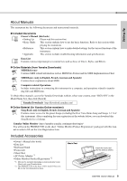
Page 11 highlights
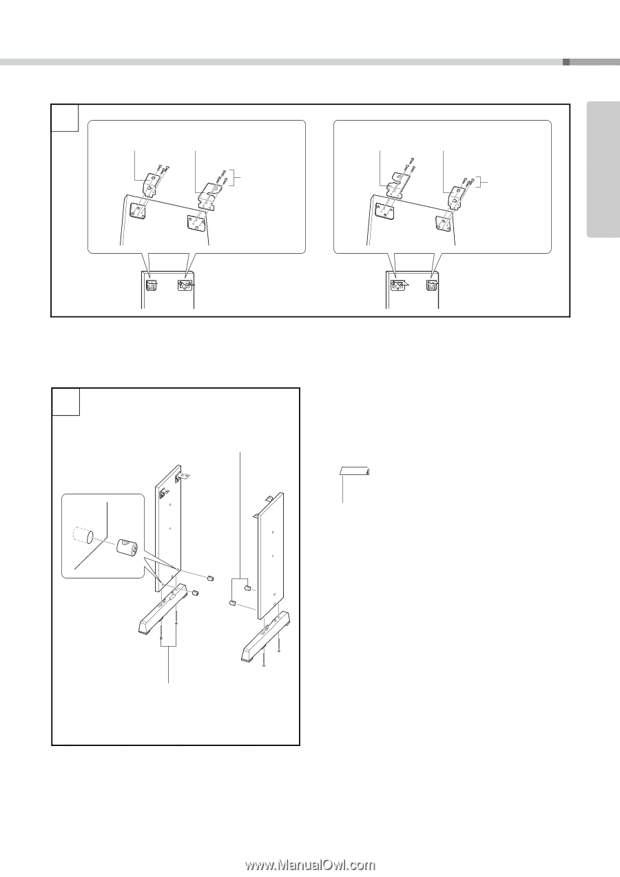
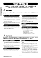
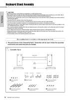
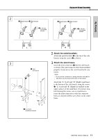
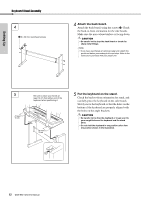
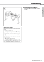
Setting Up 2 w Metal bracket w Metal bracket (C) (A) e 3 x 8 mm roundhead screws Keyboard Stand Assembly w Metal bracket w Metal bracket (B) (C) e 3 x 8 mm roundhead screws L 3 q Joint connectors "L" "R" r 6 x 70 mm roundhead screws R 2 Attach the metal brackets. Attach the metal brackets w to the top of the side boards, using the screws e as shown. 3 Attach the stand bases. Insert the joint connectors q into the side boards as shown. The joint connectors have been installed properly if you can see the screw head on the connector. NOTE • If you put the connectors in wrong direction and want to take them out, tap around the holes on the boards. Attach the "L" (Left) and "R" (Right) stand bases to the bottom of the side boards, using the screws r. "L" (Left) and "R" (Right) are marked on the upper surfaces of the stand bases. If you have trouble fastening the screws, use a screwdriver to rotate the joint connectors so that the connector holes are aligned with the screw holes on the stand bases. DGX-650 Owner's Manual 11
-
 1
1 -
2
-
3
-
4
-
5
-
 6
6 -
 7
7 -
 8
8 -
 9
9 -
 10
10 -
 11
11 -
 12
12 -
 13
13 -
 14
14 -
 15
15 -
 16
16 -
17
-
18
-
19
-
20
-
21
-
22
-
23
-
24
-
25
-
26
-
27
-
28
-
29
-
30
-
31
-
32
-
33
-
34
-
35
-
36
-
37
-
38
-
39
-
40
-
41
-
42
-
43
-
44
-
45
-
46
-
47
-
48
-
49
-
50
-
51
-
52
-
53
-
54
-
55
-
56
-
57
-
58
-
59
-
60
-
61
-
62
-
63
-
64
-
65
-
66
-
67
-
68
-
69
-
70
-
71
-
72
-
73
-
74
-
75
-
76
-
77
-
78
-
79
-
80
-
81
-
82
-
83
-
84
-
85
-
86
 |
 |