Yamaha DGX-670 DGX-670 Reference Manual - Page 83
MIDI Receive Settings, buttons to select the part via which the selected channel will
 |
View all Yamaha DGX-670 manuals
Add to My Manuals
Save this manual to your list of manuals |
Page 83 highlights
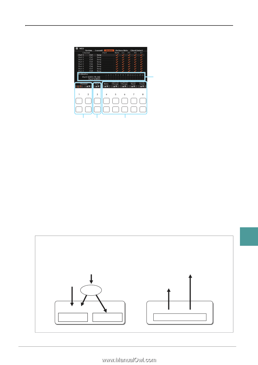
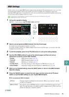
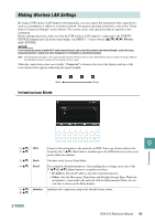
MIDI Receive Settings The explanations here apply to the Receive page in step 4 on page 79. This determines which parts will receive MIDI data and over which MIDI channels the data will be received. The dots corresponding to each channel (1-16) flash briefly whenever any data is received on the channel(s). NOTE If WLAN is shown, this instrument can handle MIDI messages received via the USB wireless LAN adaptor connected to the [USB TO DEVICE] terminal. When WLAN is not shown although the USB wireless LAN adaptor is connected, turn the instrument off then on again. 12 3 1 Use the [1 ]/[2 ] (Channel) buttons to select the channel to be received. You can use the [1 ] buttons to skip up or down through the next port, while you can use the [2 ] buttons to move up or down to the next channel one by one. The instrument can receive MIDI messages over 32 channels (16 channels x 2 ports) by USB connection. 2 Use the [3 ] (Part) buttons to select the part via which the selected channel will be received. The Parts listed on this display are the same as those shown in the Mixer display and Channel On/Off display with the exception of the following parts. • Keyboard: The received note messages control the instrument's keyboard performance. • Extra Part 1-5: There are five parts specially reserved for receiving and playing MIDI data. Normally, these parts are not used by the instrument itself. The instrument can be used as a 32-channel multitimbral tone generator by using these five parts in addition to the other parts of the instrument. 3 Use the [4 ]-[8 ] buttons to enter checkmarks to the types of data to be received. MIDI messages (page 82) with checkmarks can be received. MIDI transmission/reception via the USB terminals 9 The relationship of the USB terminals and their handling of MIDI messages (transmitting/receiving 32 channels; 16 channels x 2 ports) is shown in the following diagram: Connections MIDI reception [USB TO HOST] terminal MIDI transmission [USB TO HOST] terminal Wireless LAN Port handling USB1 USB2 Wireless LAN Merge USB1/WLAN 01-16 USB2 01-16 USB/WLAN 01-16 DGX-670 Reference Manual 83
-
 1
1 -
2
-
3
-
4
-
5
-
6
-
7
-
8
-
9
-
10
-
11
-
12
-
13
-
14
-
15
-
16
-
17
-
18
-
19
-
20
-
21
-
22
-
23
-
24
-
25
-
26
-
27
-
28
-
29
-
30
-
31
-
32
-
33
-
34
-
35
-
36
-
37
-
38
-
39
-
40
-
41
-
42
-
43
-
44
-
45
-
46
-
47
-
48
-
49
-
50
-
51
-
52
-
53
-
54
-
55
-
56
-
57
-
58
-
59
-
60
-
61
-
62
-
63
-
64
-
65
-
66
-
67
-
68
-
69
-
70
-
71
-
72
-
73
-
74
-
75
-
76
-
77
-
 78
78 -
 79
79 -
 80
80 -
 81
81 -
 82
82 -
 83
83 -
 84
84 -
 85
85 -
 86
86 -
 87
87 -
 88
88 -
89
-
90
-
91
-
92
-
93
 |
 |