Yamaha RX-V2065 Owner's Manual - Page 21
When using the AV OUT jacks, When using the AUDIO OUT jacks, When using the DIGITAL AUDIO OPTICAL
 |
UPC - 027108933948
View all Yamaha RX-V2065 manuals
Add to My Manuals
Save this manual to your list of manuals |
Page 21 highlights
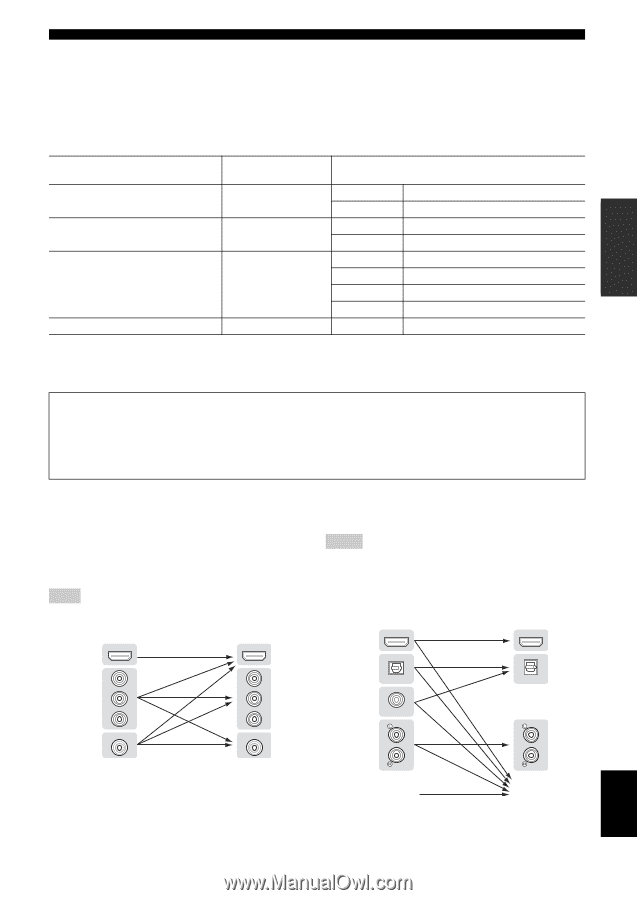
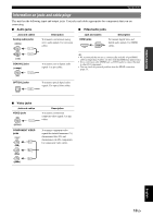
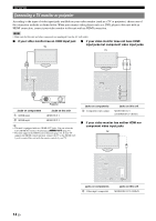
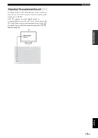
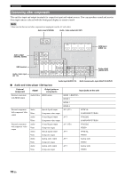
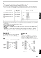
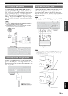
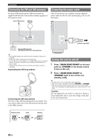
INTRODUCTION PREPARATION BASIC OPERATION Connections y • Input jacks in parentheses indicate the jacks to which the SCENE function (page 24) is assigned by the initial factory settings. To use the SCENE function with the initial factory settings, connect external components that support the SCENE function to these jacks. • You can change the name of the input source displayed on the front panel display as necessary (page 64). • See page 69 on how to use the ZONE2/3 OUT jacks. • When you connect an external component with analog audio and component video (or composite) output jacks, connect the analog audio output to the AUDIO 1 or AUDIO 2 jacks of this unit while making a video connection (component video or composite). Then select the video to be output when "AUDIO 1" or "AUDIO 2" is selected as the input source (page 56). ■ Audio player External component Output jacks on components Input jacks on this unit External component with optical digital output Optical digital output AV 1 (TV) AV 4 OPTICAL OPTICAL External component with coaxial digital output Coaxial digital output AV 2 AV 3 (CD) COAXIAL COAXIAL External component with analog audio output Analog audio output AV 5 AV 6 Analog audio Analog audio AUDIO 1 Analog audio AUDIO 2 Analog audio Turntable Analog audio output PHONO Analog audio y • If your CD player has a coaxial digital output jack, connect it to the AV3 jack of this unit. In this case, you can use the SCENE function (page 24) with the initial factory settings. • When connecting a turntable with a low-output MC cartridge to the PHONO jacks, use an in-line boosting transformer or MC-head amplifier. • Connect your turntable to the GND terminal of this unit to reduce noise in the signal. About audio/video output jacks When using the AV OUT jacks: connect these jacks to composite video and analog audio input jacks of an external component. When using the AUDIO OUT jacks: connect these jacks to analog audio input jacks of an external component. When using the DIGITAL AUDIO (OPTICAL OUT) jack: connect this jack to optical digital input jack of an external component. ■ Internal signal flow Video signal flow This unit automatically converts input video signals and outputs the signals to the HDMI OUT jacks and MONITOR OUT (COMPONENT VIDEO and VIDEO) jacks (video conversion). Note • The AV OUT (composite video) jack only outputs video signals input to the composite video input jacks. HDMI Input HDMI Output HDMI OUT PR Component video PB Y Composite VIDEO video PR PB Y VIDEO Audio signal flow Notes • Audio signals input to the HDMI input jacks are output from either the speaker terminals or HDMI OUT 1/2 jacks depending on the "Audio Output" setting (page 62). • The DIGITAL AUDIO (OPTICAL OUT) jack outputs digital audio signals only when signals are input to the optical or coaxial optical input jacks and corresponding input source is selected. HDMI Input HDMI Output HDMI OUT OUT Optical digital OPTICAL OPTICAL Coaxial digital COAXIAL Analog MULTI CH INPUT Speaker terminals ADVANCED OPERATION ADDITIONAL INFORMATION APPENDIX English 17 En
-
 1
1 -
2
-
3
-
4
-
5
-
6
-
7
-
8
-
9
-
10
-
11
-
12
-
13
-
14
-
15
-
 16
16 -
 17
17 -
 18
18 -
 19
19 -
 20
20 -
 21
21 -
 22
22 -
 23
23 -
 24
24 -
 25
25 -
 26
26 -
27
-
28
-
29
-
30
-
31
-
32
-
33
-
34
-
35
-
36
-
37
-
38
-
39
-
40
-
41
-
42
-
43
-
44
-
45
-
46
-
47
-
48
-
49
-
50
-
51
-
52
-
53
-
54
-
55
-
56
-
57
-
58
-
59
-
60
-
61
-
62
-
63
-
64
-
65
-
66
-
67
-
68
-
69
-
70
-
71
-
72
-
73
-
74
-
75
-
76
-
77
-
78
-
79
-
80
-
81
-
82
-
83
-
84
-
85
-
86
-
87
-
88
-
89
-
90
-
91
-
92
-
93
-
94
-
95
-
96
-
97
-
98
-
99
-
100
-
101
-
102
-
103
-
104
-
105
-
106
-
107
-
108
-
109
-
110
-
111
-
112
-
113
-
114
 |
 |