Yamaha RX-V2065 Owner's Manual - Page 24
Connecting the FM and AM antennas, Connecting the power cable, Turning this unit on and off
 |
UPC - 027108933948
View all Yamaha RX-V2065 manuals
Add to My Manuals
Save this manual to your list of manuals |
Page 24 highlights
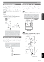
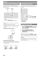
Connections Connecting the FM and AM antennas An indoor FM antenna and an AM loop antenna are supplied with this unit. Connect these antennas properly to the respective jacks. Indoor FM antenna AM loop antenna Connecting the power cable After all connections are complete, plug the supplied power cable into the AC inlet and then plug it into an AC wall outlet. (HDMI CONTROL) (BD/DVD) DOCK COMPONENT OUT VIDEO PR OPTICAL DIGITAL AUDIO GND PB Y ANTENNA HD Radio FM GND AM UNBAL. VIDEO MONITOR OUT COMPONENT VIDEO R PR IN OUT PB VIDEO Y AC IN To the AC wall outlet Ground (GND terminal) The GND terminal is for noise reduction. y • The supplied antennas are normally sensitive enough to obtain good reception. • Position the AM loop antenna away from this unit. • If you cannot get good reception, we recommend that you use an outdoor antenna. For details, consult the nearest authorized Yamaha dealer or service center. • Always use the AM loop antenna even when the outdoor antenna is connected. Assembling the AM loop antenna Connecting the AM loop antenna The wires of the AM loop antenna have no polarity. You can connect either wire to the AM terminal and the other to the GND terminal. Turning this unit on and off 1 Press LMAIN ZONE ON/OFF on the front panel (or pPOWER on the remote control) to turn on this unit. 2 Press LMAIN ZONE ON/OFF (or pPOWER) again to turn off this unit (standby mode). y • The unit needs a few seconds until ready to play back. • You can also turn on this unit by pressing RSCENE (or hSCENE). • This unit consumes a small amount of electricity even in the standby mode. We recommend disconnecting the power cable from the AC wall outlet. Caution Do not unplug this unit while it is turned on. Doing so may damage this unit or cause the settings of this unit to be saved incorrectly. Press and hold Insert Release 20 En
-
 1
1 -
2
-
3
-
4
-
5
-
6
-
7
-
8
-
9
-
10
-
11
-
12
-
13
-
14
-
15
-
16
-
17
-
18
-
 19
19 -
 20
20 -
 21
21 -
 22
22 -
 23
23 -
 24
24 -
 25
25 -
 26
26 -
 27
27 -
 28
28 -
 29
29 -
30
-
31
-
32
-
33
-
34
-
35
-
36
-
37
-
38
-
39
-
40
-
41
-
42
-
43
-
44
-
45
-
46
-
47
-
48
-
49
-
50
-
51
-
52
-
53
-
54
-
55
-
56
-
57
-
58
-
59
-
60
-
61
-
62
-
63
-
64
-
65
-
66
-
67
-
68
-
69
-
70
-
71
-
72
-
73
-
74
-
75
-
76
-
77
-
78
-
79
-
80
-
81
-
82
-
83
-
84
-
85
-
86
-
87
-
88
-
89
-
90
-
91
-
92
-
93
-
94
-
95
-
96
-
97
-
98
-
99
-
100
-
101
-
102
-
103
-
104
-
105
-
106
-
107
-
108
-
109
-
110
-
111
-
112
-
113
-
114
 |
 |
