ZyXEL GS2200-8 User Guide - Page 115
Rapid Spanning Tree Protocol Status
 |
View all ZyXEL GS2200-8 manuals
Add to My Manuals
Save this manual to your list of manuals |
Page 115 highlights
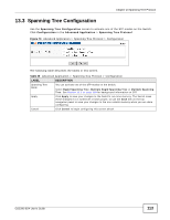
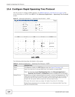
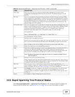
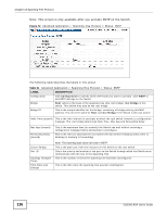
Chapter 13 Spanning Tree Protocol Table 30 Advanced Application > Spanning Tree Protocol > RSTP (continued) LABEL Hello Time DESCRIPTION This is the time interval in seconds between BPDU (Bridge Protocol Data Units) configuration message generations by the root switch. The allowed range is 1 to 10 seconds. Max Age This is the maximum time (in seconds) the Switch can wait without receiving a BPDU before attempting to reconfigure. All Switch ports (except for designated ports) should receive BPDUs at regular intervals. Any port that ages out STP information (provided in the last BPDU) becomes the designated port for the attached LAN. If it is a root port, a new root port is selected from among the Switch ports attached to the network. The allowed range is 6 to 40 seconds. Forwarding Delay This is the maximum time (in seconds) the Switch will wait before changing states. This delay is required because every switch must receive information about topology changes before it starts to forward frames. In addition, each port needs time to listen for conflicting information that would make it return to a blocking state; otherwise, temporary data loops might result. The allowed range is 4 to 30 seconds. As a general rule: Note: 2 * (Forward Delay - 1) >= Max Age >= 2 * (Hello Time + 1) Port This field displays the port number. * Settings in this row apply to all ports. Use this row only if you want to make some settings the same for all ports. Use this row first to set the common settings and then make adjustments on a port-by-port basis. Active Edge Note: Changes in this row are copied to all the ports as soon as you make them. Select this check box to activate RSTP on this port. Select this check box to configure a port as an edge port when it is directly attached to a computer. An edge port changes its initial STP port state from blocking state to forwarding state immediately without going through listening and learning states right after the port is configured as an edge port or when its link status changes. Priority Path Cost Apply Cancel Note: An edge port becomes a non-edge port as soon as it receives a Bridge Protocol Data Unit (BPDU). Configure the priority for each port here. Priority decides which port should be disabled when more than one port forms a loop in a switch. Ports with a higher priority numeric value are disabled first. The allowed range is between 0 and 255 and the default value is 128. Path cost is the cost of transmitting a frame on to a LAN through that port. It is recommended to assign this value according to the speed of the bridge. The slower the media, the higher the cost-see Table 27 on page 110 for more information. Click Apply to save your changes to the Switch's run-time memory. The Switch loses these changes if it is turned off or loses power, so use the Save link on the top navigation panel to save your changes to the non-volatile memory when you are done configuring. Click Cancel to begin configuring this screen afresh. 13.5 Rapid Spanning Tree Protocol Status Click Advanced Application > Spanning Tree Protocol in the navigation panel to display the status screen as shown next. See Section 13.1 on page 109 for more information on RSTP. GS2200-8/24 User's Guide 115
-
 1
1 -
2
-
3
-
4
-
5
-
6
-
7
-
8
-
9
-
10
-
11
-
12
-
13
-
14
-
15
-
16
-
17
-
18
-
19
-
20
-
21
-
22
-
23
-
24
-
25
-
26
-
27
-
28
-
29
-
30
-
31
-
32
-
33
-
34
-
35
-
36
-
37
-
38
-
39
-
40
-
41
-
42
-
43
-
44
-
45
-
46
-
47
-
48
-
49
-
50
-
51
-
52
-
53
-
54
-
55
-
56
-
57
-
58
-
59
-
60
-
61
-
62
-
63
-
64
-
65
-
66
-
67
-
68
-
69
-
70
-
71
-
72
-
73
-
74
-
75
-
76
-
77
-
78
-
79
-
80
-
81
-
82
-
83
-
84
-
85
-
86
-
87
-
88
-
89
-
90
-
91
-
92
-
93
-
94
-
95
-
96
-
97
-
98
-
99
-
100
-
101
-
102
-
103
-
104
-
105
-
106
-
107
-
108
-
109
-
 110
110 -
 111
111 -
 112
112 -
 113
113 -
 114
114 -
 115
115 -
 116
116 -
 117
117 -
 118
118 -
 119
119 -
 120
120 -
121
-
122
-
123
-
124
-
125
-
126
-
127
-
128
-
129
-
130
-
131
-
132
-
133
-
134
-
135
-
136
-
137
-
138
-
139
-
140
-
141
-
142
-
143
-
144
-
145
-
146
-
147
-
148
-
149
-
150
-
151
-
152
-
153
-
154
-
155
-
156
-
157
-
158
-
159
-
160
-
161
-
162
-
163
-
164
-
165
-
166
-
167
-
168
-
169
-
170
-
171
-
172
-
173
-
174
-
175
-
176
-
177
-
178
-
179
-
180
-
181
-
182
-
183
-
184
-
185
-
186
-
187
-
188
-
189
-
190
-
191
-
192
-
193
-
194
-
195
-
196
-
197
-
198
-
199
-
200
-
201
-
202
-
203
-
204
-
205
-
206
-
207
-
208
-
209
-
210
-
211
-
212
-
213
-
214
-
215
-
216
-
217
-
218
-
219
-
220
-
221
-
222
-
223
-
224
-
225
-
226
-
227
-
228
-
229
-
230
-
231
-
232
-
233
-
234
-
235
-
236
-
237
-
238
-
239
-
240
-
241
-
242
-
243
-
244
-
245
-
246
-
247
-
248
-
249
-
250
-
251
-
252
-
253
-
254
-
255
-
256
-
257
-
258
-
259
-
260
-
261
-
262
-
263
-
264
-
265
-
266
-
267
-
268
-
269
-
270
-
271
-
272
-
273
-
274
-
275
-
276
-
277
-
278
-
279
-
280
-
281
-
282
-
283
-
284
-
285
-
286
-
287
-
288
-
289
-
290
-
291
-
292
-
293
-
294
-
295
-
296
-
297
-
298
-
299
-
300
-
301
-
302
-
303
-
304
-
305
-
306
-
307
-
308
-
309
-
310
-
311
-
312
-
313
-
314
-
315
-
316
-
317
-
318
-
319
-
320
-
321
-
322
-
323
-
324
-
325
-
326
-
327
-
328
-
329
-
330
-
331
-
332
 |
 |