ZyXEL GS2200-8 User Guide - Page 78
Table 14, Label, Description
 |
View all ZyXEL GS2200-8 manuals
Add to My Manuals
Save this manual to your list of manuals |
Page 78 highlights
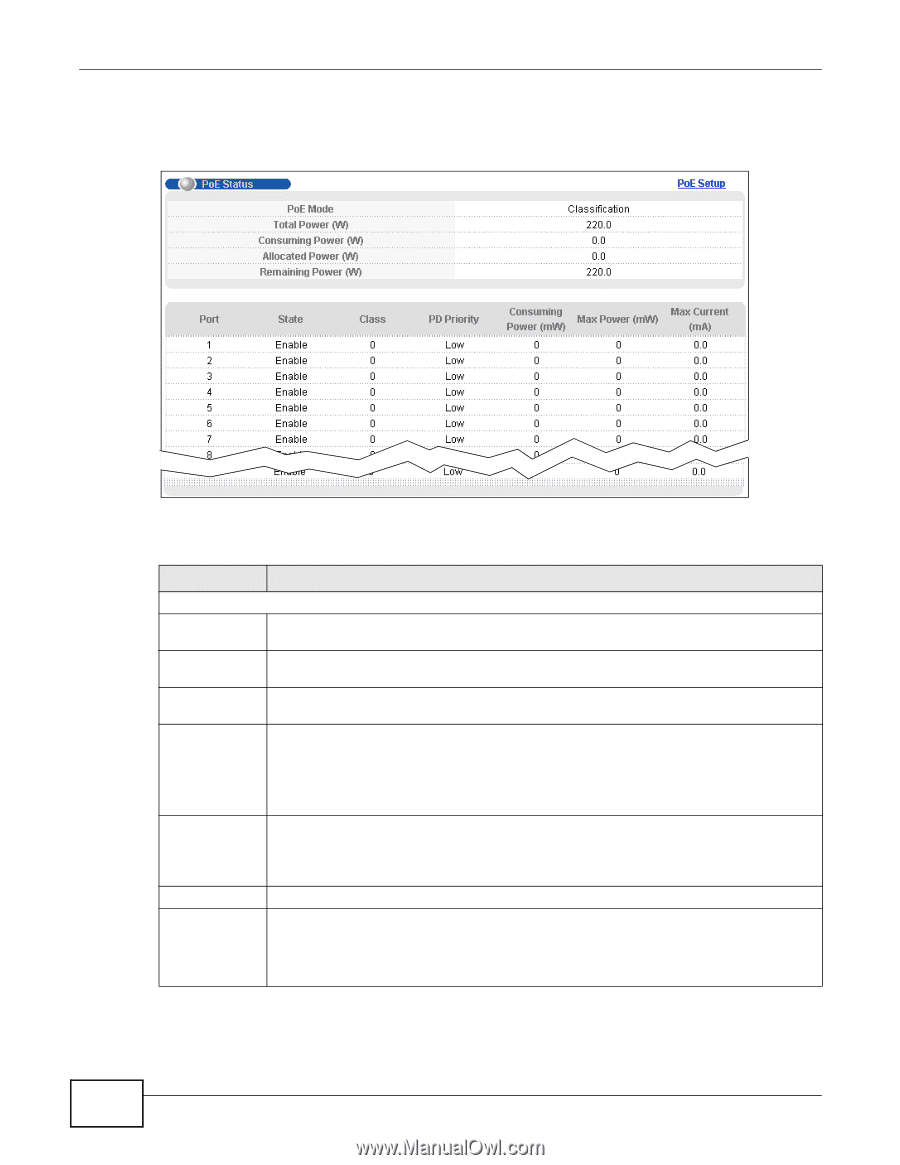
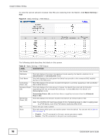
Chapter 8 Basic Setting To view the current amount of power that PDs are receiving from the Switch, click Basic Setting > PoE. Figure 47 Basic Setting > PoE Status The following table describes the labels in this screen. Table 14 Basic Setting > PoE Status LABEL PoE Status PoE Mode Total Power Consuming Power (W) Allocated Power (W) DESCRIPTION This field displays the power management mode used by the Switch, whether it is in Classification or Consumption mode. This field displays the total power the Switch can provide to the connected PoE-enabled devices on the PoE ports. This field displays the amount of power the Switch is currently supplying to the connected PoE-enabled devices. This field displays the total amount of power the Switch has reserved for PoE after negotiating with the connected PoE device(s). It shows NA when the Switch is in Consumption mode. Remaining Power (W) Port State Consuming Power (W) can be less than or equal but not more than the Allocated Power (W). This field displays the amount of power the Switch can still provide for PoE. Note: The GS2200-24P must have at least 20 W of remaining power in order to supply power to a PoE device, even if the PoE device needs less than 20 W. This is the port index number. This field shows which ports can receive power from the Switch. You can set this in Section 8.8.1 on page 79. • Disable - The PD connected to this port cannot get power supply. • Enable - The PD connected to this port can receive power. 78 GS2200-8/24 User's Guide
-
 1
1 -
2
-
3
-
4
-
5
-
6
-
7
-
8
-
9
-
10
-
11
-
12
-
13
-
14
-
15
-
16
-
17
-
18
-
19
-
20
-
21
-
22
-
23
-
24
-
25
-
26
-
27
-
28
-
29
-
30
-
31
-
32
-
33
-
34
-
35
-
36
-
37
-
38
-
39
-
40
-
41
-
42
-
43
-
44
-
45
-
46
-
47
-
48
-
49
-
50
-
51
-
52
-
53
-
54
-
55
-
56
-
57
-
58
-
59
-
60
-
61
-
62
-
63
-
64
-
65
-
66
-
67
-
68
-
69
-
70
-
71
-
72
-
 73
73 -
 74
74 -
 75
75 -
 76
76 -
 77
77 -
 78
78 -
 79
79 -
 80
80 -
 81
81 -
 82
82 -
 83
83 -
84
-
85
-
86
-
87
-
88
-
89
-
90
-
91
-
92
-
93
-
94
-
95
-
96
-
97
-
98
-
99
-
100
-
101
-
102
-
103
-
104
-
105
-
106
-
107
-
108
-
109
-
110
-
111
-
112
-
113
-
114
-
115
-
116
-
117
-
118
-
119
-
120
-
121
-
122
-
123
-
124
-
125
-
126
-
127
-
128
-
129
-
130
-
131
-
132
-
133
-
134
-
135
-
136
-
137
-
138
-
139
-
140
-
141
-
142
-
143
-
144
-
145
-
146
-
147
-
148
-
149
-
150
-
151
-
152
-
153
-
154
-
155
-
156
-
157
-
158
-
159
-
160
-
161
-
162
-
163
-
164
-
165
-
166
-
167
-
168
-
169
-
170
-
171
-
172
-
173
-
174
-
175
-
176
-
177
-
178
-
179
-
180
-
181
-
182
-
183
-
184
-
185
-
186
-
187
-
188
-
189
-
190
-
191
-
192
-
193
-
194
-
195
-
196
-
197
-
198
-
199
-
200
-
201
-
202
-
203
-
204
-
205
-
206
-
207
-
208
-
209
-
210
-
211
-
212
-
213
-
214
-
215
-
216
-
217
-
218
-
219
-
220
-
221
-
222
-
223
-
224
-
225
-
226
-
227
-
228
-
229
-
230
-
231
-
232
-
233
-
234
-
235
-
236
-
237
-
238
-
239
-
240
-
241
-
242
-
243
-
244
-
245
-
246
-
247
-
248
-
249
-
250
-
251
-
252
-
253
-
254
-
255
-
256
-
257
-
258
-
259
-
260
-
261
-
262
-
263
-
264
-
265
-
266
-
267
-
268
-
269
-
270
-
271
-
272
-
273
-
274
-
275
-
276
-
277
-
278
-
279
-
280
-
281
-
282
-
283
-
284
-
285
-
286
-
287
-
288
-
289
-
290
-
291
-
292
-
293
-
294
-
295
-
296
-
297
-
298
-
299
-
300
-
301
-
302
-
303
-
304
-
305
-
306
-
307
-
308
-
309
-
310
-
311
-
312
-
313
-
314
-
315
-
316
-
317
-
318
-
319
-
320
-
321
-
322
-
323
-
324
-
325
-
326
-
327
-
328
-
329
-
330
-
331
-
332
 |
 |