Cisco G1 Installation Guide
Cisco G1 - Network Processing Engine G1 Manual
 |
UPC - 746320679488
View all Cisco G1 manuals
Add to My Manuals
Save this manual to your list of manuals |
Cisco G1 manual content summary:
- Cisco G1 | Installation Guide - Page 1
the NPE-G1 and the NPE-G2 processors. For the Cisco 7200 VXR routers, order the NPE-G1 or NPE-G1= product. For the Cisco uBR7200 series routers, order the UBR7200-NPE-G1, UBR7200-NPE-G1=, UBR7200-NPE-G2, or UBR7200-NPE-G2= product. OL-4448-12 Network Processing Engine and Network Services Engine - Cisco G1 | Installation Guide - Page 2
the NPE-G1 or NPE-G2 is a different procedure than previous processor upgrades because of the following considerations: • The NPE-G1 and NPE-G2 contain an I/O controller, which includes the bootflash and NVRAM memory. After you install the NPE-G1 or NPE-G2 in a chassis, you can no longer access the - Cisco G1 | Installation Guide - Page 3
an Upgrade Before you install an NPE-G1 or NPE-G2 in an existing router and remove the existing processor and I/O controller, do the following: Step 1 Step 2 Step 3 Copy the configuration file from the existing router to a TFTP server, Flash Disk, or PC Card. See the "Copying the Configuration - Cisco G1 | Installation Guide - Page 4
7-7 Copying the Configuration File to a Flash Disk or PC Card Use the following instructions for copying the router configuration file to a Flash Disk or PC Card. Caution If the NPE-G1 or NPE-G2 will be installed in a router with either a C7200-I/O-GE/E or C7200-I/O-2FE/E I/O controller, copy - Cisco G1 | Installation Guide - Page 5
Disk or PC Card. Go to the "Removing the Network Processing Engine" section on page 7-7 for instructions on removing the current network processing engine or network services engine and replacing it with the NPE-G1 or NPE-G2. Copying the Configuration File to a TFTP Server Before copying the router - Cisco G1 | Installation Guide - Page 6
NPE-G1 and NPE file server.) Router# copy instructions on contacting technical assistance. This completes the procedure for copying the configuration file to a TFTP server. Proceed to "Removing the Network Processing Engine" section on page 7-7. Network Processing Engine and Network Services Engine - Cisco G1 | Installation Guide - Page 7
NPE-G2, follow the instructions in this chapter for removal of an existing network processing engine or network services engine and installation of the NPE-G1 or NPE-G2. Note If you are removing the I/O controller, and do not plan to replace it, you must install an I/O controller blank panel (Cisco - Cisco G1 | Installation Guide - Page 8
Removing the Network Processing Engine Chapter 7 NPE-G1 and NPE-G2 Installation and Configuration Information Ensuring Easy Access to the Router If your Cisco 7200 VXR router or Cisco uBR7200 series router is installed in a standard 19-inch, 4-post or telco-type rack, cables from other equipment - Cisco G1 | Installation Guide - Page 9
. The following sections provide instructions on disconnecting power from the Cisco 7200 VXR routers and Cisco uBR7200 series routers: • Disconnecting AC-Input Power from a Cisco 7200 VXR Router, page 7-9 • Disconnecting AC-Input Power from a Cisco uBR7246VXR Router, page 7-10 • Disconnecting AC - Cisco G1 | Installation Guide - Page 10
procedure for disconnecting AC-input power from a Cisco 7200 VXR router. Go to the "Removing the NPE or NSE-1" section on page 7-16. Disconnecting AC-Input Power from a Cisco uBR7246VXR Router To disconnect AC-input power from a Cisco uBR7246VXR router, complete the following steps: Step 1 Step - Cisco G1 | Installation Guide - Page 11
switch 3 Handle 3 4 Network processing engine 5 AC-input power supply Step 4 Repeat Step 1 through Step 3 if a second power supply is installed. This completes the procedure for disconnecting AC-input power from a Cisco uBR7246VXR router. Go to the "Removing the NPE or NSE-1" section on page 7-16 - Cisco G1 | Installation Guide - Page 12
Removing the Network Processing Engine Chapter 7 NPE-G1 and NPE-G2 Installation and Configuration tie from the power supply. Figure 7-3 Disconnecting Power from a Cisco 7200 VXR Router DC-Input Power Supply 1 2 66431 networking xxxx engine 1 DC-input receptacle 2 Internal fans 3 4 3 Power - Cisco G1 | Installation Guide - Page 13
Cisco 7200 VXR router. Go to the "Removing the NPE or NSE-1" section on page 7-16. Disconnecting DC-Input Power from a Cisco uBR7246VXR Router To disconnect DC-input power from a Cisco uBR7246VXR router -12 Network Processing Engine and Network Services Engine Installation and Configuration 7-13 - Cisco G1 | Installation Guide - Page 14
Network Processing Engine Chapter 7 NPE-G1 and NPE-G2 Installation and Configuration Information Figure 7-4 Removing the Strain-Relief Cover from a Cisco uBR7246VXR Router DC-Input Figure 7-5. 7-14 Network Processing Engine and Network Services Engine Installation and Configuration OL-4448-12 - Cisco G1 | Installation Guide - Page 15
above to disconnect a secure power supply. This completes the procedure for disconnecting DC-input power from a Cisco uBR7246VXR router. Go to the following section, "Removing the NPE or NSE-1." OL-4448-12 Network Processing Engine and Network Services Engine Installation and Configuration 7-15 - Cisco G1 | Installation Guide - Page 16
Removing the Network Processing Engine Chapter 7 NPE-G1 and NPE-G2 Installation and Configuration Information Removing the NPE or NSE-1 To remove the NPE or NSE-1 from a Cisco 7200 VXR router, a Cisco uBR7246VXR or a Cisco UBR7225VXR router complete the following steps. Note The weight of - Cisco G1 | Installation Guide - Page 17
shielding bag. This completes the procedure for removing an installed NPE. For instructions on installing the NPE-G1 or NPE-G2, go to the "Installing the NPE-G1 or NPE-G2" section on page 7-18. OL-4448-12 Network Processing Engine and Network Services Engine Installation and Configuration 7-17 - Cisco G1 | Installation Guide - Page 18
G1 or NPE-G2 Chapter 7 NPE-G1 and NPE-G2 Installation and Configuration Information Installing the NPE-G1 or NPE-G2 To install the NPE-G1 or NPE-G2 in the router, use the following procedures: • Basic Guidelines, page 7-18 • Installing a CompactFlash Disk, page 7-19 • Installing a USB Flash Memory - Cisco G1 | Installation Guide - Page 19
-G2" section on page 7-20. For instructions on installing a Gigabit Interface Converter (GBIC) in the NPE-G1, go to the "Installing a GBIC-NPE-G1" section on page 7-23. Installing a USB Flash Memory Module or eToken-NPE-G2 To connect a Cisco USB Flash memory module or the Aladdin USB eToken Pro key - Cisco G1 | Installation Guide - Page 20
information about the Cisco IOS commands that support USB Flash memory modules, see the Cisco USB eToken and USB Flash Features Support document. Go to the "Inserting the NPE-G1 or NPE-G2 into the Router" section on page 7-28 for instructions on installing the NPE-G1 or NPE-G2 in the chassis - Cisco G1 | Installation Guide - Page 21
Figure 7-9 Types of SFP Module Latches 1 2 Installing the NPE-G1 or NPE-G2 3 80755 1 Sliding latch 2 Swing and slide latch Warning During this procedure, wear grounding wrist straps to avoid ESD damage to the card. Do not directly touch the backplane with your hand or any metal tool, or - Cisco G1 | Installation Guide - Page 22
SFP module optical bores until you are ready to install the network interface optical fiber cable. Save the plug for future use. Note NPE-G2 into the chassis, see the "Inserting the NPE-G1 or NPE-G2 into the Router" section on page 7-28. 7-22 Network Processing Engine and Network Services Engine - Cisco G1 | Installation Guide - Page 23
Issues for Fiber-Optic Connections document. Go to the "Inserting the NPE-G1 or NPE-G2 into the Router" section on page 7-28 for instructions on installing the NPE-G1 or NPE-G2 in the chassis. OL-4448-12 Network Processing Engine and Network Services Engine Installation and Configuration 7-23 - Cisco G1 | Installation Guide - Page 24
the NPE-G1 or NPE-G2 Chapter 7 NPE-G1 and NPE-G2 Installation and Configuration Information Replacing the DIMM on the NPE-G2 To replace the DIMM on the NPE-G2, use the following instructions: Step 1 Locate the DIMM on the NPE-G2. See Figure 7-12. Figure 7-12 Locating the DIMM on the NPE-G2 - Cisco G1 | Installation Guide - Page 25
DIMM, holding it securely in place. You have finished replacing the DIMM. To install the NPE-G2 in the chassis, go to the "Inserting the NPE-G1 or NPE-G2 into the Router" section on page 7-28. OL-4448-12 Network Processing Engine and Network Services Engine Installation and Configuration 7-25 - Cisco G1 | Installation Guide - Page 26
the NPE-G1 or NPE-G2 Chapter 7 NPE-G1 and NPE-G2 Installation and Configuration Information Upgrading the SDRAM SODIMMs on the NPE-G1 (Optional) If you have purchased an SDRAM memory upgrade for the NPE-G1, replace the SDRAM SODIMMs on the NPE-G1 using the following instructions. Removing - Cisco G1 | Installation Guide - Page 27
Installing an SDRAM SODIMM Installing the NPE-G1 or NPE-G2 1 66437 1 SODIMM Step Handle SODIMMs by the edges only; avoid touching the memory modules, pins, or traces (the metal fingers you damage a socket, you will have to return the NPE-G1 to the factory for repair. Step 4 Gently press on - Cisco G1 | Installation Guide - Page 28
instructions in this section: Step 1 Align the left and right edges of the NPE-G1 or NPE-G2 with the chassis slot guides. Figure 7-16 shows an NPE-G1 being installed into a Cisco 7200 VXR router; inserting an NPE-G2 is similar. Inserting a Cisco uBR7200-NPE-G1 or Cisco uBR7200-NPE-G2 in a Cisco - Cisco G1 | Installation Guide - Page 29
brackets to the router. Go to one of these sections for instructions on rear-mounting the cable-management brackets and attaching the cables: • Installing the NPE-G1 or NPE-G2 Cable-Management Brackets, page 7-29-This procedure applies to both the Cisco 7200 VXR routers and Cisco uBR7200 series - Cisco G1 | Installation Guide - Page 30
uBR7200-NPE-G1 or Cisco uBR7200-NPE-G2 Cable-Management Bracket . 1 GIGABIT ETHERNET 0/1 LINK EN RJ45 RX GBIC TX GIGABIT ETHERNET 0/1 LINK EN RJ45 RX GBIC TX GIGABIT ETHERNET 0/1 LINK EN RJ45 RX GBIC TX NETWORK PROCESSING ENGINE - G1 CPU RESET C O M PAC T F L A S H SLOT ACTIVE - Cisco G1 | Installation Guide - Page 31
the Rear Cable-Management Brackets on a Front-Mounted Router (Optional) Use the instructions in this section to attach the cable-management brackets to a front-mounted Cisco 7200 VXR router. OL-4448-12 Network Processing Engine and Network Services Engine Installation and Configuration 7-31 - Cisco G1 | Installation Guide - Page 32
Rear Cable-Management Brackets on a Rear-Mounted Router (Optional) Use the instructions in this section to attach the cable-management brackets if you have a rear-mounted Cisco 7200 VXR router. 7-32 Network Processing Engine and Network Services Engine Installation and Configuration OL-4448-12 - Cisco G1 | Installation Guide - Page 33
Installing the NPE-G1 or NPE-G2 Figure 7-20 Installing the Rear Cable-Management Brackets with the NPE-G1 or NPE-G2-Router Rear- interface ports on the NPE-G1 or NPE-G2. Step 4 Place the cables through the cable-management brackets. OL-4448-12 Network Processing Engine and Network Services Engine - Cisco G1 | Installation Guide - Page 34
Go to the "Reconnecting Input Power and Powering Up the Router" section on page 7-35. Installing the Default Cable-Management Bracket on a Cisco uBR7246VXR Router (Optional) If you are not using the NPE-G1 Processing Engine and Network Services Engine Installation and Configuration OL-4448-12 - Cisco G1 | Installation Guide - Page 35
a Cisco 7200 VXR router, Cisco UBR7225VXR, or Cisco uBR7246VXR router, power up the router, and verify a successful system boot. Warning Read the installation instructions before you power cable. OL-4448-12 Network Processing Engine and Network Services Engine Installation and Configuration 7-35 - Cisco G1 | Installation Guide - Page 36
NPE-G1 or NPE-G2 Chapter 7 NPE-G1 and NPE-G2 Installation and Configuration Information Figure 7-24 Connecting AC-Input Power to a Cisco 7200 VXR Router Cisco 7200 VXR router. Proceed to the "Powering Up the Router" section on page 7-45. 7-36 Network Processing Engine and Network Services Engine - Cisco G1 | Installation Guide - Page 37
NPE-G1 or NPE-G2 Reconnecting AC-Input Power to the Cisco uBR7246VXR Router Figure 7-25 Connecting AC-Input Power to a Cisco uBR7246VXR Router Cisco uBR7246VXR router. Proceed to the "Powering Up the Router" section on page 7-45. OL-4448-12 Network Processing Engine and Network Services Engine - Cisco G1 | Installation Guide - Page 38
Installing the NPE-G1 or NPE-G2 Chapter 7 NPE-G1 and NPE-G2 Installation and Configuration Information Reconnecting AC-Input Power to the Cisco uBR7225VXR Router To connect AC-input power to the Cisco uBR7225VXR router, complete the following steps: Step 1 At the rear of the router, ensure that - Cisco G1 | Installation Guide - Page 39
tape the switch handle of the circuit breaker in the off position. Figure 7-27 Connecting DC-Input Power to a Cisco 7200 VXR Router 1 66432 23 4 1 Power switch 2 Ground lead service loop 3 Cable tie 4 DC power leads Step 3 If necessary, use a wire stripper to strip approximately 0.55 inch (14 - Cisco G1 | Installation Guide - Page 40
NPE-G1 or NPE-G2 Chapter 7 NPE-G1 and NPE-G2 Installation and Configuration Information Figure 7-28 Stripping the DC-Input Lines 1 57019 1 0.55 in. (14 mm) Step 4 Step 5 For the Cisco 7200 VXR routers Processing Engine and Network Services Engine Installation and Configuration OL-4448-12 - Cisco G1 | Installation Guide - Page 41
NPE-G1 or NPE-G2 This completes the steps for reconnecting DC-input power to a Cisco 7200 VXR router. Proceed to the "Powering Up the Router" section on page 7-45. Reconnecting DC-Input Power to a Cisco uBR7246VXR Router To reconnect DC-input power to a Cisco uBR7246VXR router services router services - Cisco G1 | Installation Guide - Page 42
Installing the NPE-G1 or NPE-G2 Chapter 7 NPE-G1 and NPE-G2 Installation and Configuration Information Figure 7-29 Connecting DC-Input Power to a Cisco uBR7246VXR Router 1 2 0.55 in. (14 mm) 7-42 Network Processing Engine and Network Services Engine Installation and Configuration OL-4448-12 - Cisco G1 | Installation Guide - Page 43
Chapter 7 NPE-G1 and NPE-G2 Installation and Configuration Information Installing the NPE-G1 or NPE-G2 Step 4 Step 5 Connect the two-hole grounding lug on or nut driver (or adjustable wrench). OL-4448-12 Network Processing Engine and Network Services Engine Installation and Configuration 7-43 - Cisco G1 | Installation Guide - Page 44
Step 9 if a second power supply is installed. This completes the steps for reconnecting DC-input power to a Cisco uBR7246VXR router. Proceed to the following section, "Powering Up the Router." 7-44 Network Processing Engine and Network Services Engine Installation and Configuration OL-4448-12 - Cisco G1 | Installation Guide - Page 45
cables are connected to the port adapters or I/O controller or NPE-G1 or NPE-G2 interfaces. - Each cable interface line card is inserted in its slot, and its respective captive installation screws are tightened (Cisco uBR7246VXR router only). - (Optional) A CompactFlash Disk is installed in the - Cisco G1 | Installation Guide - Page 46
the procedure for installing the NPE-G1 or NPE-G2 in a Cisco 7200 VXR router, Cisco uBR7246VXR router, or Cisco uBR7225VXR. Enabling the Second Processor on the NPE-G1 The Cisco 7200VXR NPE-G1 includes a dual-CPU-core BCM1250 processor. All Cisco IOS images for the Cisco 7200VXR NPE-G1 use CPU-core - Cisco G1 | Installation Guide - Page 47
Processor on the NPE-G1 • Upgrade the ROMmon. (The minimum ROMmon version is 12.3-4r.T3.) • Install the enabling software. Instructions for upgrading ROMmon are in the "Using the upgrade rom-monitor file Command" section on page 7-64. The minimum software release for the Broadband L2TP Access - Cisco G1 | Installation Guide - Page 48
Enabling the Second Processor on the NPE-G1 Chapter 7 NPE-G1 and NPE-G2 Installation and Configuration Information Using the show interface stats Command Use the show interface stats command for information about the interface. Router# show interface stats GigabitEthernet0/1 Switching path - Cisco G1 | Installation Guide - Page 49
Enabling the Second Processor on the NPE-G1 Using the show minutes, and 72 hours. Router# show mpf cpu history slns 0 5 0 5 0 5 0 5 0 5 0 5 0 OL-4448-12 Network Processing Engine and Network Services Engine Installation and Configuration 7-49 - Cisco G1 | Installation Guide - Page 50
Using the show mpf interface command without arguments shows the interface information for all Gigabit Ethernet interfaces and subinterfaces. This command is supported only for physical interfaces. There is no support for the virtual access interface. Router# show mpf interface Name Index State - Cisco G1 | Installation Guide - Page 51
" when processor 1 is enabled. Router# show version Cisco IOS Software, 7200 Software (C7200-I12S-M), Version 12.3(BSNOP4_NIGHTLY.050202) UBUILDIT Image, CISCO DEVELOPMENT TEST VERSION Copyright (c) 1986-2005 by Cisco Systems, Inc. OL-4448-12 Network Processing Engine and Network Services Engine - Cisco G1 | Installation Guide - Page 52
254/auto/tftpboot-users/biff/c7200-i12s-mz.2005-02-02.BSNOP4_NIGH" Last reload reason: Reload command Cisco 7206VXR (NPE-G1) processor (revision 0xFF) with 983040K/65536K bytes of memory. Processor board ID 31650243 SB-1 CPU at 700MHz, Implementation 1025, Rev 0.2, 512KB L2 Cache 6 slot VXR midplane - Cisco G1 | Installation Guide - Page 53
on the NPE-G1 or NPE-G2. Enter the copy disk2: filename command. Router# copy disk2:filename running Enter the write command: Router#: write You have finished copying and writing the saved configuration file to NVRAM. OL-4448-12 Network Processing Engine and Network Services Engine Installation - Cisco G1 | Installation Guide - Page 54
session is established to the router. • The router is connected to a network supporting a file server (remote host). • The remote host supports the TFTP application. • You have the name or address of the remote host. Before configuring the new interfaces on the NPE-G1 or NPE-G2, be prepared with the - Cisco G1 | Installation Guide - Page 55
system. This completes the procedure for downloading the saved router configuration from the remote host. Proceed to the "Configuring the Native Gigabit Ethernet Interfaces" section on page 7-56. OL-4448-12 Network Processing Engine and Network Services Engine Installation and Configuration 7-55 - Cisco G1 | Installation Guide - Page 56
port messages routed to the auxiliary port, use the Cisco IOS command terminal monitor on the auxiliary port on which you desire to receive console messages. Router# terminal monitor Configuring the Native Gigabit Ethernet Interfaces The NPE-G1 and NPE-G2 report both the RJ-45 and GBIC or SFP - Cisco G1 | Installation Guide - Page 57
default to 1000 Mbps. Both full-duplex and half-duplex operations are supported in this mode. Sample Configuration for the Gigabit Ethernet Interfaces The following shows a typical configuration for the three Gigabit Ethernet interfaces on the NPE-G1. The same configuration would be typical for the - Cisco G1 | Installation Guide - Page 58
command output to Cisco for analysis. Resetting the Interface Should you have a problem with your interface and wish to try and reset it, use the command: clear interface GigabitEthernet 0/X (where X is 1, 2, or 3) 7-58 Network Processing Engine and Network Services Engine Installation and - Cisco G1 | Installation Guide - Page 59
router, to verify the operation status, to view interface configuration settings, and to troubleshoot your router configuration. The interfaces on the NPE-G1 and NPE a single MII Fast Ethernet receptacle only. Although still supported by Cisco, this I/O controller with a single MII receptacle is no - Cisco G1 | Installation Guide - Page 60
omitted) Cisco 7206VXR (NPE-G2) processor (revision A) with 917504K/131072K bytes of memory. Processor board ID 32428149 MPC7448 CPU at 1660Mhz, Implementation 0, Rev 2.0 6 slot VXR midplane, Version 2.8 (display text omitted) 7-60 Network Processing Engine and Network Services Engine Installation - Cisco G1 | Installation Guide - Page 61
interface controllers. The following example provides information about the interfaces on the I/O controller C7200-I/O-2FE/E and the NPE-G1 installed in a Cisco 7206VXR router: Router# show controllers Interface hang never Last clearing of "show interface" counters 21:18:23 Queueing strategy:fifo - Cisco G1 | Installation Guide - Page 62
.com and copy the new boot helper image to flash memory on your router. For information on how to access Cisco.com, see the "Obtaining Documentation and Submitting a Service Request" section on page -iv. Follow the Software Center link under Service and Support. You need to get a login code from - Cisco G1 | Installation Guide - Page 63
a new ROMmon image instead of having to replace hardware (NPE-G1 or NPE-G2) to get a new image. Note ROMmon can be upgraded on the NPE-G1 or NPE-G2, but cannot be upgraded on any other network processor engine for the Cisco 7200 series routers. There are two ROMmon images: one ReadOnly image (the - Cisco G1 | Installation Guide - Page 64
NPE-G1 or NPE-G2 Chapter 7 NPE-G1 and NPE-G2 Installation and Configuration Information Using the show rom-monitor Command and ROMmon CLI showmon Commands Use the show rom-monitor command if you are in Cisco : Router# cisco Systems, Inc. 7-64 Network Processing Engine and Network Services Engine - Cisco G1 | Installation Guide - Page 65
Chapter 7 NPE-G1 and NPE-G2 Installation and Configuration Information Troubleshooting the Upgrade Running new upgrade for first time System Bootstrap, Version 12.2(20031011:151758) [biff] Copyright (c) 1994-2003 by cisco Systems, Inc. ROM:Rebooted by watchdog hard reset C7200 platform with - Cisco G1 | Installation Guide - Page 66
(c) 1994-2003 by cisco Systems, Inc. Upgrade ROMMON corrupted. Falling to ReadOnly ROMMON ROM:Rebooted by watchdog hard reset C7200 platform with 1048576 Kbytes of main memory Readonly ROMMON initialized 7-66 Network Processing Engine and Network Services Engine Installation and Configuration OL - Cisco G1 | Installation Guide - Page 67
Cisco IOS Release 12.4(4)XD, only a manual FPD upgrade of the NPE-G2 is supported. For FPGA upgrade information and procedures, see the Field-Programmable Device Upgrades document at: http://www.cisco.com/en/US/docs/routers/7200/configuration/feature_guides/fpd.html Troubleshooting the NPE-G1 or NPE - Cisco G1 | Installation Guide - Page 68
Fiber Optic Cleaning Information Chapter 7 NPE-G1 and NPE-G2 Installation and Configuration Information 7-68 Network Processing Engine and Network Services Engine Installation and Configuration OL-4448-12
-
 1
1 -
 2
2 -
 3
3 -
 4
4 -
 5
5 -
 6
6 -
 7
7 -
8
-
9
-
10
-
11
-
12
-
13
-
14
-
15
-
16
-
17
-
18
-
19
-
20
-
21
-
22
-
23
-
24
-
25
-
26
-
27
-
28
-
29
-
30
-
31
-
32
-
33
-
34
-
35
-
36
-
37
-
38
-
39
-
40
-
41
-
42
-
43
-
44
-
45
-
46
-
47
-
48
-
49
-
50
-
51
-
52
-
53
-
54
-
55
-
56
-
57
-
58
-
59
-
60
-
61
-
62
-
63
-
64
-
65
-
66
-
67
-
68
 |
 |

CH A P T E R
7-1
Network Processing Engine and Network Services Engine Installation and Configuration
OL-4448-12
7
NPE-G1 and NPE-G2 Installation and
Configuration Information
This chapter provides information on installing and configuring the NPE-G1 and NPE-G2 and contains
the following sections:
•
Preparing for an Upgrade, page 7-2
•
Copying the Configuration File, page 7-4
•
Removing the Network Processing Engine, page 7-7
•
Installing the NPE-G1 or NPE-G2, page 7-18
•
Enabling the Second Processor on the NPE-G1, page 7-46
•
Copying the Saved Configuration to NVRAM, page 7-52
•
Auxiliary and Console Port Information, page 7-56
•
Configuring the Native Gigabit Ethernet Interfaces, page 7-56
•
Using show Commands to Check the Installation, page 7-59
•
Upgrading the Cisco IOS Image and the Boot Helper (Boot Loader) Image, page 7-62
•
Upgrading ROMmon on the NPE-G1 or NPE-G2, page 7-63
•
Troubleshooting the Upgrade, page 7-65
•
Upgrading FPGA on the NPE-G2, page 7-67
•
Troubleshooting the NPE-G1 or NPE-G2, page 7-67
•
Fiber Optic Cleaning Information, page 7-67
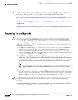
Note
The Cisco
7200
VXR routers and Cisco
uBR7200 series routers use different models of the NPE-G1 and
the NPE-G2 processors. For the Cisco 7200 VXR routers, order the NPE-G1 or NPE-G1= product. For
the Cisco uBR7200 series routers, order the UBR7200-NPE-G1, UBR7200-NPE-G1=,
UBR7200-NPE-G2, or UBR7200-NPE-G2= product.