Cisco G1 Installation Guide - Page 33
Installing the Rear Cable-Management Brackets with the NPE-G1 or NPE-G2-Router
 |
UPC - 746320679488
View all Cisco G1 manuals
Add to My Manuals
Save this manual to your list of manuals |
Page 33 highlights
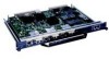
Chapter 7 NPE-G1 and NPE-G2 Installation and Configuration Information Installing the NPE-G1 or NPE-G2 Figure 7-20 Installing the Rear Cable-Management Brackets with the NPE-G1 or NPE-G2-Router Rear-Mounted 66750 EN 1 GIGABIT ETHERNET 0/1 LINK EN RJ45 RX GBIC TX GIGABIT ETHERNET 0/1 LINK EN RJ45 RX GBIC TX GIGABIT ETHERNET 0/1 LINK EN RJ45 RX GBIC TX NETWORK PROCESSING ENGINE - G1 CPU RESET C O M PAC T F L A S H 1 SLOT ACTIVE POWER ON CONSOLE AUX 1 Screws Step 1 Align the cable-management brackets with the rack-mount brackets as shown in Figure 7-20. Step 2 Insert and tighten two screws for each bracket. The screws come with the cable-management brackets. Figure 7-21 Attaching Console and Auxiliary Port Cables NETWORK CPU RESET PROCESSING ENGINE - G1 COMPACT FLASH 12 ASCLTOI VTE POWER ON CONSOLE AUX 66777 3 4 5 1 Console port 2 Auxiliary port 3 RJ-45 connectors 4 Cable to console terminal or DTE 5 Cable to modem or DCE Step 3 Insert the console and auxiliary RJ-45 cables into the interface ports on the NPE-G1 or NPE-G2. Step 4 Place the cables through the cable-management brackets. OL-4448-12 Network Processing Engine and Network Services Engine Installation and Configuration 7-33
-
 1
1 -
2
-
3
-
4
-
5
-
6
-
7
-
8
-
9
-
10
-
11
-
12
-
13
-
14
-
15
-
16
-
17
-
18
-
19
-
20
-
21
-
22
-
23
-
24
-
25
-
26
-
27
-
 28
28 -
 29
29 -
 30
30 -
 31
31 -
 32
32 -
 33
33 -
 34
34 -
 35
35 -
 36
36 -
 37
37 -
 38
38 -
39
-
40
-
41
-
42
-
43
-
44
-
45
-
46
-
47
-
48
-
49
-
50
-
51
-
52
-
53
-
54
-
55
-
56
-
57
-
58
-
59
-
60
-
61
-
62
-
63
-
64
-
65
-
66
-
67
-
68
 |
 |
