Cisco G1 Installation Guide - Page 44
Replacing the Strain-Relief Cover on a Cisco uBR7246VXR Series DC-Input Power, Supply
 |
UPC - 746320679488
View all Cisco G1 manuals
Add to My Manuals
Save this manual to your list of manuals |
Page 44 highlights
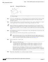
Installing the NPE-G1 or NPE-G2 Chapter 7 NPE-G1 and NPE-G2 Installation and Configuration Information Figure 7-31 Replacing the Strain-Relief Cover on a Cisco uBR7246VXR Series DC-Input Power Supply 1 2 3 8 4 5 66409 1 Power switch 2 Power receptacle 3 Captive installation screw 4 M5 grounding receptacles 5 M5 grounding lug Step 9 Restore current to the -V and +V leads. 6 7 9 6 -V lead 7 +V lead 8 Strain-relief cover 9 M4 nuts Note For the Cisco uBR7200 series routers, each DC-input power supply rating is 14A, 700 volt ampere (VA). This product relies on the building's installation for short-circuit (overcurrent) protection. Ensure that a listed and certified fuse or circuit breaker, 35A minimum 60 VDC, is used on all current-carrying conductors. Site wiring and circuit breakers need to be sized to accommodate the maximum values for safety reasons. Step 10 Repeat Step 1 through Step 9 if a second power supply is installed. This completes the steps for reconnecting DC-input power to a Cisco uBR7246VXR router. Proceed to the following section, "Powering Up the Router." 7-44 Network Processing Engine and Network Services Engine Installation and Configuration OL-4448-12
-
 1
1 -
2
-
3
-
4
-
5
-
6
-
7
-
8
-
9
-
10
-
11
-
12
-
13
-
14
-
15
-
16
-
17
-
18
-
19
-
20
-
21
-
22
-
23
-
24
-
25
-
26
-
27
-
28
-
29
-
30
-
31
-
32
-
33
-
34
-
35
-
36
-
37
-
38
-
 39
39 -
 40
40 -
 41
41 -
 42
42 -
 43
43 -
 44
44 -
 45
45 -
 46
46 -
 47
47 -
 48
48 -
 49
49 -
50
-
51
-
52
-
53
-
54
-
55
-
56
-
57
-
58
-
59
-
60
-
61
-
62
-
63
-
64
-
65
-
66
-
67
-
68
 |
 |
