Cisco G1 Installation Guide - Page 31
Installing the Rear Cable-Management Brackets on a Front-Mounted Router (Optional)
 |
UPC - 746320679488
View all Cisco G1 manuals
Add to My Manuals
Save this manual to your list of manuals |
Page 31 highlights
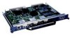
Chapter 7 NPE-G1 and NPE-G2 Installation and Configuration Information Installing the NPE-G1 or NPE-G2 Step 1 Step 2 Step 3 Step 4 Step 5 Step 6 Loosen the left and right captive installation screws on the NPE-G1 or NPE-G2. Hold the cable-management bracket so that it is positioned above the NPE-G1 or NPE-G2 captive installation screws as shown in Figure 7-17 and Figure 7-18. The bracket is properly positioned when the horizontally-faced notch is at the left, the vertically-faced notch is at the right, and the bracket's outer edge is flush with the edge on the NPE-G1 or NPE-G2. If you reverse the bracket so that it is not flush with the NPE-G1 or NPE-G2, you will not be able to access the GBIC or SFP module connectors on the NPE-G1 or NPE-G2 front panel. Slide the left end of the bracket between the captive installation screw and the front panel of the NPE-G1 or NPE-G2. Rotate the cable-management bracket down, until its other notch slides behind the right captive installation screw. Make sure the bracket's outer edge is flush with the edge of the NPE-G1 or NPE-G2 and does not obstruct the GBIC or SFP ports. Tighten both captive installation screws. Install the cables, and fasten them to the bracket with the velcro straps provided. Installing the Rear Cable-Management Brackets on a Front-Mounted Router (Optional) Use the instructions in this section to attach the cable-management brackets to a front-mounted Cisco 7200 VXR router. OL-4448-12 Network Processing Engine and Network Services Engine Installation and Configuration 7-31
-
 1
1 -
2
-
3
-
4
-
5
-
6
-
7
-
8
-
9
-
10
-
11
-
12
-
13
-
14
-
15
-
16
-
17
-
18
-
19
-
20
-
21
-
22
-
23
-
24
-
25
-
 26
26 -
 27
27 -
 28
28 -
 29
29 -
 30
30 -
 31
31 -
 32
32 -
 33
33 -
 34
34 -
 35
35 -
 36
36 -
37
-
38
-
39
-
40
-
41
-
42
-
43
-
44
-
45
-
46
-
47
-
48
-
49
-
50
-
51
-
52
-
53
-
54
-
55
-
56
-
57
-
58
-
59
-
60
-
61
-
62
-
63
-
64
-
65
-
66
-
67
-
68
 |
 |
