Cisco G1 Installation Guide - Page 28
Inserting the NPE-G1 or NPE-G2 into the Router,
 |
UPC - 746320679488
View all Cisco G1 manuals
Add to My Manuals
Save this manual to your list of manuals |
Page 28 highlights
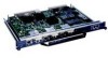
Installing the NPE-G1 or NPE-G2 Chapter 7 NPE-G1 and NPE-G2 Installation and Configuration Information Step 5 If the SODIMM appears misaligned, carefully remove it and reseat it in the socket. Push the SODIMM gently back into the socket until the spring latches snap into place. You have finished replacing the SDRAM SODIMM. To install the NPE-G1 in the chassis, go to the "Inserting the NPE-G1 or NPE-G2 into the Router" section on page 7-28. Inserting the NPE-G1 or NPE-G2 into the Router Note If you have difficulty installing a network processing engine or I/O controller in the lowest slot of a Cisco 7200 VXR router that is rack-mounted, remove the port adapters, network processing engine and I/O controller from the chassis and reinstall them. Install the network processing engine and I/O controller in the lowest slots first, then populate the slots above them, in a bottom-to-top order. To insert the NPE-G1 or NPE-G2 into the router, follow the instructions in this section: Step 1 Align the left and right edges of the NPE-G1 or NPE-G2 with the chassis slot guides. Figure 7-16 shows an NPE-G1 being installed into a Cisco 7200 VXR router; inserting an NPE-G2 is similar. Inserting a Cisco uBR7200-NPE-G1 or Cisco uBR7200-NPE-G2 in a Cisco uBR7200 series router is similar. Figure 7-16 Aligning the NPE-G1 Between the Slot Guides on a Cisco 7200 VXR Router 66773 1 GIGABIT ETHERNET 0/1 LINK EN RJ45 RX GBIC TX GIGABIT ETHERNET 0/1 LINK EN RJ45 RX GBIC TX GIGABIT ETHERNET 0/1 LINK EN RJ45 RX GBIC TX NETWORK PROCESSING ENGINE - G1 CPU RESET C O M PAC T F L A S H SLOT ACTIVE POWER ON CONSOLE AUX 2 1 Slot guides 2 NPE-G1 3 4 3 Printed circuit board 4 Metal carrier Step 2 Step 3 Gently slide the NPE-G1 or NPE-G2 all the way into its chassis slot until you feel the connectors seat with the router midplane. Seat the NPE-G1 or NPE-G2 in the router midplane by tightening its captive installation screws with a number 2 Phillips or a 3/16-inch flat-blade screwdriver. 7-28 Network Processing Engine and Network Services Engine Installation and Configuration OL-4448-12
-
 1
1 -
2
-
3
-
4
-
5
-
6
-
7
-
8
-
9
-
10
-
11
-
12
-
13
-
14
-
15
-
16
-
17
-
18
-
19
-
20
-
21
-
22
-
 23
23 -
 24
24 -
 25
25 -
 26
26 -
 27
27 -
 28
28 -
 29
29 -
 30
30 -
 31
31 -
 32
32 -
 33
33 -
34
-
35
-
36
-
37
-
38
-
39
-
40
-
41
-
42
-
43
-
44
-
45
-
46
-
47
-
48
-
49
-
50
-
51
-
52
-
53
-
54
-
55
-
56
-
57
-
58
-
59
-
60
-
61
-
62
-
63
-
64
-
65
-
66
-
67
-
68
 |
 |
