Cisco G1 Installation Guide - Page 14
Removing the Strain-Relief Cover from a Cisco uBR7246VXR Router DC-Input Power, Supply
 |
UPC - 746320679488
View all Cisco G1 manuals
Add to My Manuals
Save this manual to your list of manuals |
Page 14 highlights
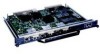
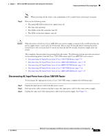
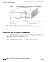
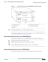
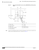
Removing the Network Processing Engine Chapter 7 NPE-G1 and NPE-G2 Installation and Configuration Information Figure 7-4 Removing the Strain-Relief Cover from a Cisco uBR7246VXR Router DC-Input Power Supply 1 2 8 3 9 4 5 1 Power switch 2 Power receptacle 3 Captive screw 4 M5 grounding receptacles 5 M5 grounding lug 7 6 6 -V lead 7 +V lead 8 Strain-relief cover 9 M4 nuts and studs 66408 Step 4 Using a 3/16-inch flat-blade screwdriver, loosen the screw below the +V lead receptacle and pull the lead from the connector. Repeat this step for the -V lead only. See Figure 7-5. 7-14 Network Processing Engine and Network Services Engine Installation and Configuration OL-4448-12
-
 1
1 -
2
-
3
-
4
-
5
-
6
-
7
-
8
-
 9
9 -
 10
10 -
 11
11 -
 12
12 -
 13
13 -
 14
14 -
 15
15 -
 16
16 -
 17
17 -
 18
18 -
 19
19 -
20
-
21
-
22
-
23
-
24
-
25
-
26
-
27
-
28
-
29
-
30
-
31
-
32
-
33
-
34
-
35
-
36
-
37
-
38
-
39
-
40
-
41
-
42
-
43
-
44
-
45
-
46
-
47
-
48
-
49
-
50
-
51
-
52
-
53
-
54
-
55
-
56
-
57
-
58
-
59
-
60
-
61
-
62
-
63
-
64
-
65
-
66
-
67
-
68
 |
 |

7-14
Network Processing Engine and Network Services Engine Installation and Configuration
OL-4448-12
Chapter 7
NPE-G1 and NPE-G2 Installation and Configuration Information
Removing the Network Processing Engine
Figure 7-4
Removing the Strain-Relief Cover from a Cisco uBR7246VXR Router DC-Input Power
Supply
Step 4
Using a 3/16-inch flat-blade screwdriver, loosen the screw below the +V lead receptacle and pull the lead
from the connector. Repeat this step for the –V lead only. See
Figure 7-5
.
1
Power switch
6
–V lead
2
Power receptacle
7
+V lead
3
Captive screw
8
Strain-relief cover
4
M5 grounding receptacles
9
M4 nuts and studs
5
M5 grounding lug
66408
3
5
7
6
8
1
2
9
4