Cisco G1 Installation Guide - Page 42
Connecting DC-Input Power to a Cisco uBR7246VXR Router, Stripping the DC-Input Lines
 |
UPC - 746320679488
View all Cisco G1 manuals
Add to My Manuals
Save this manual to your list of manuals |
Page 42 highlights
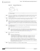
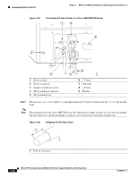
Installing the NPE-G1 or NPE-G2 Chapter 7 NPE-G1 and NPE-G2 Installation and Configuration Information Figure 7-29 Connecting DC-Input Power to a Cisco uBR7246VXR Router 1 2 9 3 66407 4 5 1 Power switch 2 Power receptacle 3 Captive installation screw 4 M5 grounding receptacles 5 M5 grounding lug 7 8 6 6 -V lead 7 M4 studs 8 +V lead 9 Handle Step 3 SIf necessary, use a wire stripper to strip approximately 0.55 inch (14 mm) from the -V, +V, and ground leads. Note The ground lead for the Cisco uBR7200 series DC-input power supply consists of a two-hole grounding lug that connects to an M5 grounding receptacle; you do not need to strip this ground lead. Figure 7-30 Stripping the DC-Input Lines 1 57019 1 0.55 in. (14 mm) 7-42 Network Processing Engine and Network Services Engine Installation and Configuration OL-4448-12
-
 1
1 -
2
-
3
-
4
-
5
-
6
-
7
-
8
-
9
-
10
-
11
-
12
-
13
-
14
-
15
-
16
-
17
-
18
-
19
-
20
-
21
-
22
-
23
-
24
-
25
-
26
-
27
-
28
-
29
-
30
-
31
-
32
-
33
-
34
-
35
-
36
-
 37
37 -
 38
38 -
 39
39 -
 40
40 -
 41
41 -
 42
42 -
 43
43 -
 44
44 -
 45
45 -
 46
46 -
 47
47 -
48
-
49
-
50
-
51
-
52
-
53
-
54
-
55
-
56
-
57
-
58
-
59
-
60
-
61
-
62
-
63
-
64
-
65
-
66
-
67
-
68
 |
 |
