Cisco G1 Installation Guide - Page 13
Disconnecting DC-Input Power from a Cisco uBR7246VXR Router, Step 5, Warning
 |
UPC - 746320679488
View all Cisco G1 manuals
Add to My Manuals
Save this manual to your list of manuals |
Page 13 highlights
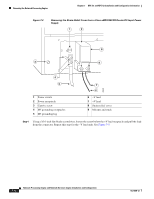
Chapter 7 NPE-G1 and NPE-G2 Installation and Configuration Information Removing the Network Processing Engine Step 5 Repeat this step for the -V lead and the ground lead. Note The color coding of the DC-input power supply leads depends on the color coding of the DC power source at your site. Typically, green or green and yellow are used for ground. Make certain that the lead color coding you choose for the DC-input power supply matches the lead color coding used at the DC power source. Step 6 Repeat Step 1 through Step 6 if a second power supply is installed. This completes the procedure for disconnecting DC-input power from a Cisco 7200 VXR router. Go to the "Removing the NPE or NSE-1" section on page 7-16. Disconnecting DC-Input Power from a Cisco uBR7246VXR Router To disconnect DC-input power from a Cisco uBR7246VXR router, complete the following steps. Warning Before completing any of the following steps, and to prevent short-circuit or shock hazards, ensure that power is removed from the DC circuit. To ensure that all power is OFF, locate the circuit breaker on the panel board that services the DC circuit, switch the circuit breaker to the OFF position, and tape the switch handle of the circuit breaker in the OFF position. Statement 322 Warning When you install the unit, the ground connection must always be made first and disconnected last. Statement 42 Step 1 Step 2 Step 3 At the rear of the router, check that the power switch on the power supply is in the off (O) position. Ensure that no current is running through the -V and +V leads. To ensure that all power is off, locate the circuit breaker on the panel board that services the DC circuit, switch the circuit breaker to the off position, and tape the switch handle of the circuit breaker in the off position. Use a 7-mm wrench or nut driver (or adjustable wrench) to loosen and remove the two M4 nuts from the strain-relief cover that secures the -V and the +V leads to the power supply faceplate. See Figure 7-4. OL-4448-12 Network Processing Engine and Network Services Engine Installation and Configuration 7-13
-
 1
1 -
2
-
3
-
4
-
5
-
6
-
7
-
 8
8 -
 9
9 -
 10
10 -
 11
11 -
 12
12 -
 13
13 -
 14
14 -
 15
15 -
 16
16 -
 17
17 -
 18
18 -
19
-
20
-
21
-
22
-
23
-
24
-
25
-
26
-
27
-
28
-
29
-
30
-
31
-
32
-
33
-
34
-
35
-
36
-
37
-
38
-
39
-
40
-
41
-
42
-
43
-
44
-
45
-
46
-
47
-
48
-
49
-
50
-
51
-
52
-
53
-
54
-
55
-
56
-
57
-
58
-
59
-
60
-
61
-
62
-
63
-
64
-
65
-
66
-
67
-
68
 |
 |
