Dell External OEMR R410 Owners Manual - Page 101
Installing the Integrated Storage Controller Card, STORAGE_PCIE
 |
View all Dell External OEMR R410 manuals
Add to My Manuals
Save this manual to your list of manuals |
Page 101 highlights
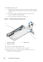
Installing the Integrated Storage Controller Card WARNING: Only trained service technicians are authorized to remove the system cover and access any of the components inside the system. Before you begin this procedure, review the safety instructions that came with the system. 1 Turn off the system, including any attached peripherals, and disconnect the system from the electrical outlet. 2 Open the system. See "Opening the System" on page 82. 3 If installed, remove the expansion card. See "Removing an Expansion Card" on page 99. 4 To install the controller card in the expansion slot on the riser labeled "STORAGE_PCIE": a Hold the card by its edges. b Insert the card-edge connector firmly into the expansion-card connector until the card is fully seated and the plastic card guide fits over the edges of the card. 5 Connect the card to the SAS backplane: a Connect the SAS data cable connector to the integrated storage controller card. See Figure 3-12. NOTE: Be sure to connect the cable according to the connector labels on the cable. The cable will not function properly if reversed. b Route the SAS data cable through the channel on the inner side of the chassis. c Attach the connector labeled "SAS A" to connector SAS A on the backplane, and attach the connector labeled "SAS B" to connector SAS B on the backplane. See Figure 3-12. Close the system. See "Closing the System" on page 83. 6 Reconnect the system to its electrical outlet and turn the system on, including any attached peripherals. Installing System Components 101
-
 1
1 -
2
-
3
-
4
-
5
-
6
-
7
-
8
-
9
-
10
-
11
-
12
-
13
-
14
-
15
-
16
-
17
-
18
-
19
-
20
-
21
-
22
-
23
-
24
-
25
-
26
-
27
-
28
-
29
-
30
-
31
-
32
-
33
-
34
-
35
-
36
-
37
-
38
-
39
-
40
-
41
-
42
-
43
-
44
-
45
-
46
-
47
-
48
-
49
-
50
-
51
-
52
-
53
-
54
-
55
-
56
-
57
-
58
-
59
-
60
-
61
-
62
-
63
-
64
-
65
-
66
-
67
-
68
-
69
-
70
-
71
-
72
-
73
-
74
-
75
-
76
-
77
-
78
-
79
-
80
-
81
-
82
-
83
-
84
-
85
-
86
-
87
-
88
-
89
-
90
-
91
-
92
-
93
-
94
-
95
-
 96
96 -
 97
97 -
 98
98 -
 99
99 -
 100
100 -
 101
101 -
 102
102 -
 103
103 -
 104
104 -
 105
105 -
 106
106 -
107
-
108
-
109
-
110
-
111
-
112
-
113
-
114
-
115
-
116
-
117
-
118
-
119
-
120
-
121
-
122
-
123
-
124
-
125
-
126
-
127
-
128
-
129
-
130
-
131
-
132
-
133
-
134
-
135
-
136
-
137
-
138
-
139
-
140
-
141
-
142
-
143
-
144
-
145
-
146
-
147
-
148
-
149
-
150
-
151
-
152
-
153
-
154
-
155
-
156
-
157
-
158
-
159
-
160
-
161
-
162
-
163
-
164
-
165
-
166
-
167
-
168
-
169
-
170
-
171
-
172
-
173
-
174
-
175
-
176
-
177
-
178
-
179
-
180
-
181
-
182
-
183
-
184
-
185
-
186
-
187
-
188
-
189
-
190
 |
 |
