Dell External OEMR R410 Owners Manual - Page 97
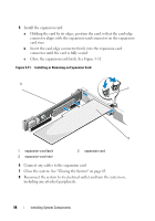
Installing an Expansion Card, Open the expansion-card latch and remove the filler bracket. See
 |
View all Dell External OEMR R410 manuals
Add to My Manuals
Save this manual to your list of manuals |
Page 97 highlights
Table 3-1. Expansion-Card Installation Order Card Priority Card Type Max 25-W Slot Priority Allowed Card? 1 SAS 6/iR Modular 2 1 Y 2 PERC 6/i 1 1 Y 3 PERC 6/E controller 1 1 Y 4 SAS 5/E 1 1 Y 5 SCSI controllers 1 1 Y 6 HPCC 1 1 Y 7 Fibre Channel 1 1 Y 8 10 Gb NIC 1 1 Y 9 All other Dell storage cards 1 1 Y 10 All other NICs 1 1 N* 11 Non-Dell storage cards 1 1 N* * Refer to the expansion card's documentation to determine if the maximum power exceeds 15W. Any cards that exceed 15W will be affected by the restriction of one 25W card. Installing an Expansion Card WARNING: Only trained service technicians are authorized to remove the system cover and access any of the components inside the system. Before you begin this procedure, review the safety instructions that came with the system. 1 Unpack the expansion card and prepare it for installation. For instructions, see the documentation accompanying the card. 2 Turn off the system, including any attached peripherals, and disconnect the system from the electrical outlet. 3 Open the system. See "Opening the System" on page 82. 4 Open the expansion-card latch and remove the filler bracket. See Figure 3-11. Installing System Components 97
-
 1
1 -
2
-
3
-
4
-
5
-
6
-
7
-
8
-
9
-
10
-
11
-
12
-
13
-
14
-
15
-
16
-
17
-
18
-
19
-
20
-
21
-
22
-
23
-
24
-
25
-
26
-
27
-
28
-
29
-
30
-
31
-
32
-
33
-
34
-
35
-
36
-
37
-
38
-
39
-
40
-
41
-
42
-
43
-
44
-
45
-
46
-
47
-
48
-
49
-
50
-
51
-
52
-
53
-
54
-
55
-
56
-
57
-
58
-
59
-
60
-
61
-
62
-
63
-
64
-
65
-
66
-
67
-
68
-
69
-
70
-
71
-
72
-
73
-
74
-
75
-
76
-
77
-
78
-
79
-
80
-
81
-
82
-
83
-
84
-
85
-
86
-
87
-
88
-
89
-
90
-
91
-
 92
92 -
 93
93 -
 94
94 -
 95
95 -
 96
96 -
 97
97 -
 98
98 -
 99
99 -
 100
100 -
 101
101 -
 102
102 -
103
-
104
-
105
-
106
-
107
-
108
-
109
-
110
-
111
-
112
-
113
-
114
-
115
-
116
-
117
-
118
-
119
-
120
-
121
-
122
-
123
-
124
-
125
-
126
-
127
-
128
-
129
-
130
-
131
-
132
-
133
-
134
-
135
-
136
-
137
-
138
-
139
-
140
-
141
-
142
-
143
-
144
-
145
-
146
-
147
-
148
-
149
-
150
-
151
-
152
-
153
-
154
-
155
-
156
-
157
-
158
-
159
-
160
-
161
-
162
-
163
-
164
-
165
-
166
-
167
-
168
-
169
-
170
-
171
-
172
-
173
-
174
-
175
-
176
-
177
-
178
-
179
-
180
-
181
-
182
-
183
-
184
-
185
-
186
-
187
-
188
-
189
-
190
 |
 |
