Epson FX-1050 User Manual - Page 133
Installing the board, the board
 |
View all Epson FX-1050 manuals
Add to My Manuals
Save this manual to your list of manuals |
Page 133 highlights
Installing the board There are two basic interface board designs. These boards differ with respect to how the frame ground (FG) wire is attached. This slight difference changes the way the boards are installed in the printer, but does not affect the operation of the interface in any way. Look at the following illustration to see which type of interface board you have and then follow the installation procedure for that type of board. FG wire not attached See below FG wire not attached 1. Use the CC screw to attach the round end of the FG (frame ground) wire to the main board and position the other end as shown. 7-28 Using Printer Options
-
 1
1 -
2
-
3
-
4
-
5
-
6
-
7
-
8
-
9
-
10
-
11
-
12
-
13
-
14
-
15
-
16
-
17
-
18
-
19
-
20
-
21
-
22
-
23
-
24
-
25
-
26
-
27
-
28
-
29
-
30
-
31
-
32
-
33
-
34
-
35
-
36
-
37
-
38
-
39
-
40
-
41
-
42
-
43
-
44
-
45
-
46
-
47
-
48
-
49
-
50
-
51
-
52
-
53
-
54
-
55
-
56
-
57
-
58
-
59
-
60
-
61
-
62
-
63
-
64
-
65
-
66
-
67
-
68
-
69
-
70
-
71
-
72
-
73
-
74
-
75
-
76
-
77
-
78
-
79
-
80
-
81
-
82
-
83
-
84
-
85
-
86
-
87
-
88
-
89
-
90
-
91
-
92
-
93
-
94
-
95
-
96
-
97
-
98
-
99
-
100
-
101
-
102
-
103
-
104
-
105
-
106
-
107
-
108
-
109
-
110
-
111
-
112
-
113
-
114
-
115
-
116
-
117
-
118
-
119
-
120
-
121
-
122
-
123
-
124
-
125
-
126
-
127
-
 128
128 -
 129
129 -
 130
130 -
 131
131 -
 132
132 -
 133
133 -
 134
134 -
 135
135 -
 136
136 -
 137
137 -
 138
138 -
139
-
140
-
141
-
142
-
143
-
144
-
145
-
146
-
147
-
148
-
149
-
150
-
151
-
152
-
153
-
154
-
155
-
156
-
157
-
158
-
159
-
160
-
161
-
162
-
163
-
164
-
165
-
166
-
167
-
168
-
169
-
170
-
171
-
172
-
173
-
174
-
175
-
176
-
177
-
178
-
179
-
180
-
181
-
182
-
183
-
184
-
185
-
186
-
187
-
188
-
189
-
190
-
191
-
192
-
193
-
194
-
195
-
196
-
197
-
198
-
199
-
200
-
201
-
202
-
203
-
204
-
205
-
206
-
207
-
208
-
209
-
210
-
211
-
212
-
213
-
214
-
215
-
216
-
217
-
218
-
219
-
220
-
221
 |
 |

Installing
the board
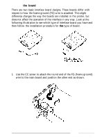
There are two basic interface board designs. These boards differ with
respect to how the frame ground (FG) wire is attached. This slight
difference changes the way the boards are installed in the printer, but
does not affect the operation of the interface in any way. Look at the
following illustration to see which type of interface board you have and
then follow the installation procedure for
that
type of board.
FG wire not attached
See below
FG wire not attached
1.
Use the CC screw to attach the round end of the FG (frame ground)
wire to the main board and position the other end as shown.
7-28
Using Printer Options