Epson TM U200D Technical Reference
Epson TM U200D - B/W Dot-matrix Printer Manual
 |
View all Epson TM U200D manuals
Add to My Manuals
Save this manual to your list of manuals |
Epson TM U200D manual content summary:
- Epson TM U200D | Technical Reference - Page 1
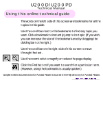
U200D/U200PD Technical Manual Using this online technical guide The words on the left side of this screen are bookmarks for all the topics in this guide. Use the scroll bar next to the bookmarks to find any topic you want. Click a bookmark to instantly jump to its topic. (If you wish, - Epson TM U200D | Technical Reference - Page 2
technical manual TM-U200D/U200PD EPSON English 4005680 - Epson TM U200D | Technical Reference - Page 3
product or unauthorized modifications, repairs, or alterations to this product, or (excluding the U.S.) failure to strictly comply with Seiko Epson Corporation's operating and maintenance instructions. Seiko Epson Corporation shall not be liable against any damages or problems arising from the use - Epson TM U200D | Technical Reference - Page 4
EPSON SEIKO EPSON CORPORATION Printed in Japan E9608130-0000SE - Epson TM U200D | Technical Reference - Page 5
TM-U200D/U200PD Technical Manual FCC CLASS A FCC Compliance Statement For American Users installed and used in accordance with the instruction manual, user will be required to correct the interference at his own expense. WARNING The connection of a non-shielded printer interface cable to this printer - Epson TM U200D | Technical Reference - Page 6
Introduction The TM-U200D and TM-U200PD are one-station printers for ECR and POS use which can be used for printing the results of weighing or measuring. The main features of the TM-U200D and TM-U200PD printers are the following: t High-speed printing through logic-seeking control t Excellent - Epson TM U200D | Technical Reference - Page 7
Notes and Cautions Note: Notes have important information and useful tips on the operation of your printer. CAUTION: Cautions must be observed to avoid damage to your equipment. Rev. B iii - Epson TM U200D | Technical Reference - Page 8
Revision Sheet Revision Rev. B Page All Altered Item and Contents Added information of the 2-color Print Version iv Rev. B - Epson TM U200D | Technical Reference - Page 9
TM-U200D/U200PD Technical Manual Chapter 1 Features and General Specifications Features 1-3 Printing Specifications 1-3 Character Specifications 1-4 Paper 1-6 Paper Roll Supply Device 1-7 Receive Buffer 1-7 Electrical Specifications 1-8 Ribbon Cassette 1-8 External Dimensions and Weight 1-9 - Epson TM U200D | Technical Reference - Page 10
-out drive circuit 2-23 DIP switch read circuit 2-24 Printer Mechanism Drive Circuit 2-25 Print head drive circuit 2-25 Chapter 3 Handling and Maintenance Handling Precautions 3-1 Storage Precautions 3-1 Use Precautions 3-1 Paper Handling Precautions 3-1 Ribbon Cassette Handling Precautions - Epson TM U200D | Technical Reference - Page 11
TM-U200D/U200PD Technical Manual Chapter 4 Troubleshooting Self-test 4-1 Initiating the Self-test 4-1 Self-test Standby 4-1 Ending the Self-test 4-2 Troubleshooting Flowchart 4-3 Troubleshooting Tables 4-9 Error Types and Countermeasures 4-14 Chapter 5 Disassembly, Assembly, and Adjustment - Epson TM U200D | Technical Reference - Page 12
Assembly 4 (Case Unit 5-32 Inserting the cables 5-32 Main Assembly 5 (Case Unit 5-32 Case, lower 5-32 Main Assembly 6 (Case Unit 5-34 Manual cutter 5-34 Main Assembly 7 (Case Unit 5-35 Paper roll receive rollers, Case, upper, Roller, guide and Switch panel 5-35 Main Assembly 8 (Case Unit - Epson TM U200D | Technical Reference - Page 13
Manual Chapter 1 Features and General Specifications FEED button ERROR LED Power switch POWER LED PAPER OUT LED (PAPER OUT/PRESS FEED) P-ROM Power supply connector Drawer kick-out connector Frame ground screw Interface connector Frame ground screw DIP switches Figure 1-1 TM-U200D/U200PD - Epson TM U200D | Technical Reference - Page 14
144 inch by using commands. Friction feed Approximately 4.17 inches/second (25 lines/second) during continuous paper feeding See the table in the next page. See the table in the next page. 7 x . It is caused by the switching operation in the printer. 1-2 Features and General Specifications Rev.B - Epson TM U200D | Technical Reference - Page 15
TM-U200D/U200PD Technical Manual CPI = Characters per inch Character dimensions, half dots depending on the setting of DIP switch 2-1. 2color printing. Black and red colors are selectable. (2-color Print Version only) Character Specifications Character set: Alphanumeric: 95 International: - Epson TM U200D | Technical Reference - Page 16
0.353 mm (0.014") 2.4 mm (0.094") 1.24 mm (0.049") 1.59 mm (0.063") 3.1 mm (0.122") Figure 1-3 Character size (7 x 9 font example) 1-4 Features and General Specifications Rev.B - Epson TM U200D | Technical Reference - Page 17
Paper Paper types: Paper roll width: Paper roll maximum diameter: Paper roll core: Normal paper: Pressure-sensitive paper Copy capability and ambient temperature for printing: TM-U200D/U200PD Technical Manual Paper roll: Plain paper Pressure-sensitive paper Features and General Specifications 1-5 - Epson TM U200D | Technical Reference - Page 18
1-4 Printing area (*1) This dimension shows the distance from the manual cutter to the printing position. (*2) The values shown for Paper Roll Supply Device Supply device: Drop-in loading Receive Buffer Either 1 KB or 40 bytes selectable by DIP switches. 1-6 Features and General Specifications - Epson TM U200D | Technical Reference - Page 19
Electrical Specifications Power supply: TM-U200D/U200PD Technical Manual One of the following five AC adapters is included, depending on the specifications: AC adapter specifications Settings and shipment Input voltage range Model name Japan 100V ± 10% 50/60 Hz PA-6508 North America 120V ± - Epson TM U200D | Technical Reference - Page 20
Color: EPSON standard gray. Environmental Specifications Temperature: Operating: 0° to 50° C (32° to 122° F) At 34° C (93° F) or higher, there are humidity restrictions; please see the figure below. Storage: -10° to 50° C (14° to 122° F) (except paper and ribbon - Epson TM U200D | Technical Reference - Page 21
Impact resistance: Reliability Printer mechanism: MCBF: Life: Print head life: TM-U200D/U200PD Technical Manual When packed: Package: EPSON standard package Height: 60 cm (23.62") Directions: 1 corner, 3 edges, and 6 surfaces When unpacked: Height: 5 cm (1.97") Directions: Lift one edge and release - Epson TM U200D | Technical Reference - Page 22
Paper detector switch sub-ass'y Print head unit Detector sub-ass'y Motor, paper feed Motor, carriage Paper roll near-end detector(N.E-U200); (optional) Interface circuit board Main circuit board Figure 1-6 TM-U200D/U200PD main unit configuration 1-10 Features and General Specifications - Epson TM U200D | Technical Reference - Page 23
TM-U200D/U200PD Technical Manual Main Unit Specifications Motor, Paper Feed Type: 4-phase, PM type stepping motor Drive voltage: 24V DC ± 10% Winding resistance: 58 Ω ± 2.9 Ω at 25° 5V DC ± 5% Low when the carriage home position is detected Rev. B Features and General Specifications 1-11 - Epson TM U200D | Technical Reference - Page 24
Paper Detector Switch Sub-ass'y Type: Microswitch Voltage: 5V DC ± 5% Output level: High when paper end is detected Near-end Detector (N.E.-U200); (Optional) Type: Microswitch Voltage: 5V DC ± 5% Output level: Low when a paper section. 1-12 Features and General Specifications Rev.B - Epson TM U200D | Technical Reference - Page 25
TM-U200D/U200PD Technical Manual Power Supply Connector This connector is used to connect the printer to an external power source. Pin assignments: See the table below. Model (printer side level: LOW = 0 V HIGH = 2 to 5V (at connector pin 3) Rev. B Features and General Specifications 1-13 - Epson TM U200D | Technical Reference - Page 26
NOTES: t Two driver transistors cannot be energized simultaneously. t The drawer drive duty must be as shown below: ON time (ON time + OFF time) ≤ 0.2 t Be sure to use the printer power supply (connector pin 4) for the drawer power source. 1-14 Features and General Specifications Rev.B - Epson TM U200D | Technical Reference - Page 27
word lengths: Parity settings: Stop bits: Connector: TM-U200D/U200PD Technical Manual Serial (compatible with RS-232) Asynchronous DTR/DSR rate, and parity depend on DIP switch settings. t Data transmitted from the printer has 1 stop bit (fixed). Rev. B Features and General Specifications 1-15 - Epson TM U200D | Technical Reference - Page 28
TM-U200D printer DIP switch setting enables this signal to be used as a reset signal for the printer (see the DIP switch settings in the "Buttons and Switches" section of this chapter). The printer is reset when the signal remains SPACE for 1 ms or more. 1-16 Features and General Specifications - Epson TM U200D | Technical Reference - Page 29
TM-U200D/U200PD Technical Manual NOTES: t When the remaining space in the receive buffer is 16 bytes, the printer becomes buffer-full. This status continues until the space in the receive buffer increases to 32 bytes. t The printer ignores the data received when the remaining space in the receive - Epson TM U200D | Technical Reference - Page 30
turning on the power and initializing the printer. RS-485 Serial Interface (option) Refer to the Appendix for details. IEEE 1284 Parallel Interface Copyright (C) 1994 by the Institute of electrical and Electronic Engineers, Inc. Specification Data transmission: 8-bit parallel Synchronization - Epson TM U200D | Technical Reference - Page 31
TM-U200D/U200PD Technical Manual The both modes fail to be proceeded concurrently with the Compatibility Mode, thereby causing half duplex transmission. The IEEE 1284 Nibble/Byte Modes are under - Epson TM U200D | Technical Reference - Page 32
Pin Assignments TM-U200PD printer status and printer shall be made after verifying the nAck signal or while the Busy signal is at the "L" level.) t Interface cables shall be as minimum required short in length as possible. NC: No Connect ND: No Defined 1-20 Features and General Specifications - Epson TM U200D | Technical Reference - Page 33
TM-U200D/U200PD Technical Manual Switching between on-line and off-line The printer is not equipped with any on-line/off-line switch. The printer is placed into off-line status in either of the followings: t When the power is turned on or until the printer becomes ready for data transmission after - Epson TM U200D | Technical Reference - Page 34
paper end, or paper is fed using the FEED button. When setting DIP switch 1-8 to ON to enable handshaking with the printer, be sure to check the printer printer is busy and if an error occurs, DLE EOT and DLE ENQ cannot be used when printer be lost. Example: Check the printer status using GS r after - Epson TM U200D | Technical Reference - Page 35
Buttons and Switches Power Switch Type: Function: TM-U200D/U200PD Technical Manual See-saw type The power switch turns the power on or off. Note: Turn on the power only after connecting the power supply. RAM is completely initialized when the printer is turned off using the power switch. Panel - Epson TM U200D | Technical Reference - Page 36
on again or reset. t Do not change the settings of DIP switches 2-3 and 2-4 when the printer power is on. Parallel interface (IEEE 1284) The DIP switches of are located at the bottom of the case. DIP switch 1 DIP Switch Function 1 Auto line feed 2 Receive buffer 3-7 Undefined 8 Busy - Epson TM U200D | Technical Reference - Page 37
TM-U200D/U200PD Technical Manual . DIP switch 2 DIP Switch Function 1 Print column selection 7 ! 9 font/9 ! 9 font 2 Internal use (*1) 3 Undefined 4 I/FnInit reset signall ON 42CPL/35CPL Enabled OFF 40CPL/33CPL Disabled NOTES: t Do not change the setting of DIP switch 2-2 (fixed to OFF - Epson TM U200D | Technical Reference - Page 38
the Self Test The printer has a self-test function that checks the following: t Control circuit functions t Printer mechanisms t Print quality t Control ROM version t DIP switch settings. See Chapter 4 for instructions on running a self-test. 1-26 Features and General Specifications Rev.B - Epson TM U200D | Technical Reference - Page 39
TM-U200D/U200PD Technical Manual Error Processing Printer Operation When an Error Occurs The printer executes the following operations upon detecting an error: t All mechanical operations stop t Goes off-line (if DIP switch 1-8 is set to OFF) t The ERROR LED blinks. Error recovery The TM-U200D - Epson TM U200D | Technical Reference - Page 40
Set DIP switch 1-2 to on to select 40 bytes for the receive buffer capacity. 3. Turn the power on while pressing the FEED button. 4. Before finishing the initialization of the printer, release the FEED button, then press the FEED button again. The printer first prints "Hexadecimal Dump" on the paper - Epson TM U200D | Technical Reference - Page 41
TM-U200D/U200PD Technical Manual External Power Supply PS-170 Specifications 100V, 120V, or 230V (specified at time of purchase) Input Conditions Input voltage (rating) Frequency (rating) Input current (rating) AC switch Energizing LED 90 to 264 V (100VAC - 10% to 230VAC + 15%) 108 V AC to 132 V - Epson TM U200D | Technical Reference - Page 42
TM-U200D/U200PD Technical Manual Chapter 2 Mechanism Configuration and Operating Principles Printer Mechanism Operating Principles The printer mechanism M-U200 mounted in the TM-U200D/U200PD is composed of four mechanisms: print, paper feed, ribbon feed, and detector. In addition to the above four - Epson TM U200D | Technical Reference - Page 43
unit consists of the parts shown in the figure below. Shaft, carriage Print head unit Pulley, belt tension Belt Frame, paper feed ass'y Shaft, carriage guide Carriage subass'y Earth plate, print head ass'y Motor, carriage ass'y FFC, print head Figure 2-2 Print mechanism unit 2-2 Mechanism - Epson TM U200D | Technical Reference - Page 44
TM-U200D/U200PD Technical Manual Print head unit movement When the Motor, carriage is driven and the portion of the Frame, paper feed being struck by the wires during printing. Actuating plate Wire return spring Ink ribbon B Paper roll Wire A Wire guide Iron core Platen Drive coil Figure - Epson TM U200D | Technical Reference - Page 45
by energizing the print solenoids with respect to the Carriage sub-ass'y portion (the reference timing for the print solenoids is the Motor, carriage phase switching signals). The print head unit is moved 0.317 mm (0.012") (in approximately 1.05 ms) each time the Motor, carriage is rotated one step - Epson TM U200D | Technical Reference - Page 46
TM-U200D/U200PD Technical Manual Paper Feed Mechanism Unit The paper feed mechanism unit consists of the parts shown in the figure below. Paper feeding is performed by driving the Motor, paper feed (stepping motor). Spring, paper hold Roller, paper hold Roller, paper feed ass'y Paper feed, upper - Epson TM U200D | Technical Reference - Page 47
(semi-automatic loading) When the paper roll is manually inserted into the Roller, paper feed , the paper detection switch in the paper path detects the paper, and semi-automatic loading (*) is executed. (*) Semi-automatic loading is the function that automatically feeds the paper to the top of the - Epson TM U200D | Technical Reference - Page 48
TM-U200D/U200PD Technical Manual During printing, the Motor, paper feed is driven after each line is printed, causing the paper to be fed a specified amount. While the FEED button on the switch panel is pressed, the Motor, paper feed is driven and the paper roll is fed. Paper roll Roller, paper - Epson TM U200D | Technical Reference - Page 49
forward. Then the ribbon feed and ribbon hold rollers in the Ribbon cassette , which are engaged with the Ribbon take-up ass'y , rotate and the ribbon is fed. Gear, carriage motor FA Gear, ribbon intermediate B Gear, ribbon drive C D G Ribbon take-up ass'y Gear, ribbon transmission Figure 2-10 - Epson TM U200D | Technical Reference - Page 50
TM-U200D/U200PD Technical Manual Detection Mechanism Unit The detection mechanism unit consists of the home position detection, paper detection, and near-end detection (optional) mechanisms. Paper to detect the movement of the Carriage subass'y. Printer side The light is The light is blocked not - Epson TM U200D | Technical Reference - Page 51
microswitch off and generates a signal indicating that the paper roll is near its end. Paper roll Case, case Microswitch Lever, N.E. detection Paper roll center Figure 2-13 N.E. detection mechanism Ribbon Switch Mechanism Unit The ribbon switch mechanism unit consists of the Motor, carriage ass - Epson TM U200D | Technical Reference - Page 52
TM-U200D/U200PD Technical Manual Switching from Black to Red When the Carriage, sub-ass'y (print head unit) moves in the E direction and reaches the ribbon switch area, the Lever, ribbon switch is pushed by the ribbon switch section and moved to position A (shown by the dotted lines). The Frame, - Epson TM U200D | Technical Reference - Page 53
Electrical Circuitry Operating Principles Hardware Configuration Component connection diagram The electrical circuitry of the printer consists of the main circuit board and the interface circuit boards (UB-S01/RS-232, UB-P01/1284, or UB-S02/RS-485). The figure - Epson TM U200D | Technical Reference - Page 54
TM-U200D/U200PD Technical Manual Circuit board block diagram The main circuit board unit contains the following Drawer kick-out drive circuit t Print head drive circuit t Motor, paper feed drive circuit t DIP switch read circuit t Various detector circuits t Motor, carriage drive circuit The - Epson TM U200D | Technical Reference - Page 55
the circuit block diagram for the printer. AC adapter ior PS |150 j DKD I/F circuit board CN2 CN1 Host interface Print head CN1 CN7 CN11 CN2 CN4 Main circuit board CN8 CN9 CN5 CN6 Carriage motor Near-end detector (optionValar)ious sensors (Not used) Paper feed motor Figure 2-16 - Epson TM U200D | Technical Reference - Page 56
TM-U200D/U200PD Technical Manual Memory Map The following parts are mapped on the printer memory map: t CPU t EPROM (Program) External program memory 0000H Program, character generator area FFFFH 0000H External data memory (For multi-lingual) Character generator area (1) FFFFH - Epson TM U200D | Technical Reference - Page 57
switching method, and is attached to the main circuit board.The following sections describe the power supply circuitry for the printer. circuit board Operation panel circuit Various detector circuits +24V Printer: Motor, carriage Motor, paper feed Print head Drawer kick-out drive Filter circuit - Epson TM U200D | Technical Reference - Page 58
TM-U200D/U200PD Technical Manual +5V DC control circuit The +5V regulator circuit switches the +24V power input and converts it to +5V. The switching regulator IC (U1) switches the +24V input, smooths it via C1, and outputs +5V. Power for the RS-232 is generated by the internal charge-up circuit on - Epson TM U200D | Technical Reference - Page 59
: IEEE 1284 parallel interface: Two signals can be selected (DSR signal or pin 25 input signal). Pin 25 RESET signal must be used. DIP switch 2-4 is fixed to ON. The printer can be reset with the nInit signal (pin 31) from the host. CN4 #RST 29 DSR_RESET 28 #25_RESET 27 DSW2 D16 3 4 D1 - Epson TM U200D | Technical Reference - Page 60
TM-U200D/U200PD Technical Manual CPU pin functions Pin CPU No. Function Signal software) External memory address A17 (software) External memory address A18 (software) Watch dog timer error (and hardware limited time power supply switch) Low: error (reset) Connected to pin #19 Paper feed switch - Epson TM U200D | Technical Reference - Page 61
Motor, carriage drive control 2-2 phase excitation All the terminals on (low): hold DIP SW 1-1to 1-4 read when P100, P101 is low Motor, paper feed drive control 2-2 phase excitation All the terminals on (low): hold DIP SW 1-5 to 1-8 read when P100, P101 is low External memory data read signal - Epson TM U200D | Technical Reference - Page 62
TM-U200D/U200PD Technical Manual CPU pin functions Pin CPU No. Function Signal Name I/O 70 P46 HEAD2 paper feed power switch Low: motor drive HOST interface CLK REQ GND terminal Host interface RTS Low: on PAPER OUT LED Low: on DIP SW 2-2 read when P100 is low ROM (512K bit) The printer - Epson TM U200D | Technical Reference - Page 63
U5. Switch detection is also executed by the U5. +5V U5 P82 32 PF SW P57/T03 1 ELED/DSW9 80 PLED/DSW0 Q35 P56/INT3/TI2 R54 1 (POWER) D13 2 Q36 R55 1 (PAPER) D12 2 R41 R15 R56 1 (ERROR) C17 D11 2 SW2 GND Figure 2-20 Operation panel circuit Various detector circuits When the printer - Epson TM U200D | Technical Reference - Page 64
TM-U200D/U200PD Technical Manual Host interface circuit The printer has the universal interfaces for connection to the host computer. There are three kinds of the interfaces: t EIA/TIA RS-232 Interface (TM-U200D) t IEEE 1284 Interface (*1) (TM-U200PD) (*1) Copyright 1994 by the Institute of - Epson TM U200D | Technical Reference - Page 65
, and pins 1 and 81 are also used for the Motor, carriage drive circuit, Motor, paper feed drive circuit, and operation panel control circuit. The pins are used to read DIP switches temporarily immediately after the printer initialization (or the power is turned on). {5V ( (*11)) U5 52 P20 53 P21 - Epson TM U200D | Technical Reference - Page 66
TM-U200D/U200PD Technical Manual Printer Mechanism Drive Circuit Print head drive circuit The head In order to prevent damage to the head during excessive printing, a heat Detector has been installed in the print head. An analog-digital conversion of the partial pressure difference between the heat - Epson TM U200D | Technical Reference - Page 67
speed of changing P90, P91, P92 and P93 between High and Low. At the end of paper feeding, P53 of the CPU is once again set to High. U5 P90/M10 56 P92 of changing P20, P21, P22, and P23 between High and Low. At the end of paper feeding, P52 of the CPU is once again set to High. +24B U5 P20/M00 52 - Epson TM U200D | Technical Reference - Page 68
Chapter 3 Handling and Maintenance TM-U200D/U200PD Technical Manual Handling Precautions Storage Precautions t Avoid storing the printer in a dusty, humid, or extremely cold area. Also avoid areas that are exposed to direct sunlight for long periods of time. t For long-term storage, - Epson TM U200D | Technical Reference - Page 69
re-ink a ribbon. If a ribbon is re-inked: q Print quality could deteriorate due to a malfunction of the print wires q Ink may leak. Replacing the Paper Roll Note: Be sure to use roll paper that meets the specifications. 1. Turn on the printer. 2. Remove the Cover, printer. 3. Pull the paper and cut - Epson TM U200D | Technical Reference - Page 70
TM-U200D/U200PD Technical Manual 6. Using scissors, cut the leading edge of the paper roll perpendicular to the paper feed direction, as shown below. 7. Insert the paper roll. Note: Be sure to note the correct direction that the paper comes off the roll, as shown below. Rev. B Handling and - Epson TM U200D | Technical Reference - Page 71
insert it straight into the paper slot. The printer feeds the paper automatically. 9. Tear off the paper, as shown below, and then close the Printer cover . 10. When the PAPER OUT light blinks, press the FEED button to set the printer on line. Replacing the Ribbon Cassette CAUTION: Make sure the - Epson TM U200D | Technical Reference - Page 72
TM-U200D/U200PD Technical Manual CAUTION: Never turn the ribbon cassette's feed knob in the opposite direction of the arrow marked on the cassette; otherwise the ribbon cassette may be damaged. 4. Insert the ribbon in the position shown in the illustration below and push the ribbon cassette until it - Epson TM U200D | Technical Reference - Page 73
you reach into the printer. 1. Turn the printer off and remove the Printer cover . 2. Pull the paper and cut it at the position shown by the dotted line in the illustration below. Cut here 3. Remove the paper roll. 4. Remove the ribbon cassette from the printer. 3-6 Handling and Maintenance Rev - Epson TM U200D | Technical Reference - Page 74
TM-U200D/U200PD Technical Manual 5. Untighten the konb of the Frame, ribbon (Thumb-screw) to unlock the Frame, ribbon . Frame, ribbon knob Thumb-screw (Single-color Print Version) (2-color-Print Version) 6. Remove the Frame, ribbon from the printer by sliding it in the direction of the arrow. Slide - Epson TM U200D | Technical Reference - Page 75
found. Check the printer following the Troubleshooting flowcharts in Chapter 4. Shape of the springs No spring should be bent or deformed. Replace any deformed springs. Ribbon cassette The ribbon cassette should be properly installed in the printer. See "Replacing the Ribbon Cassette" in this - Epson TM U200D | Technical Reference - Page 76
TM-U200D/U200PD Technical Manual Cleaning 1. Wipe off stains printer at its initial performance level throughout its product life, as well as avoiding potential problems. EPSON selection of lubricants prescribed for use with the printer is based on the results of such research. The prescribed EPSON - Epson TM U200D | Technical Reference - Page 77
) (2) Shaft, ribbon intermediate gear (3) Shaft, paper hold roller (4) Both ends of the guide roller (5) Switching points of Lever, ribbon switch (6) Switching point of Lever, ribbon release Lubricant type O-10 G-31 G-31 G-31 G-31 G-31 Tool List The required tools for this printer are as - Epson TM U200D | Technical Reference - Page 78
Lubricant and adhesive list Lubricants and adhesives Type/name Grease/G-31 Oil/O-10 Quantity 40gr 40gr TM-U200D/U200PD Technical Manual Rev. B Handling and Maintenance 3-11 - Epson TM U200D | Technical Reference - Page 79
Chapter 4 Troubleshooting TM-U200D/U200PD Technical Manual Use the following to troubleshoot and repair the printer: Self-test Use the self-test to check the operation of the control circuitry and the printer mechanism. Troubleshooting flowchart When the source of the problem is not clear, use the - Epson TM U200D | Technical Reference - Page 80
Ending the Self-test The printer prints "*** completed *** " and ends the self-test. The printer automatically becomes ready to receive data after the self-test. Figure 4-1 Self-test print out 4-2 Troubleshooting Rev.B - Epson TM U200D | Technical Reference - Page 81
TM-U200D/U200PD Technical Manual Troubleshooting Flowchart If the source of a problem is not clear, use the flowchart below to find and replace a defective component. Normally, servicing should be performed by component replacement. Repairs of the PCBs and other components should be performed only - Epson TM U200D | Technical Reference - Page 82
have proper output No voltage rating? (approx. +40 V in no-load condition) Yes Has fuse F1 on Yes main PCB blown? No Connect power supply cable properly. No OK? Yes End Replace external power supply. No OK? Yes End Replace Fuse F1 (See Replacing the fuse in Chapter 5) No OK? Yes - Epson TM U200D | Technical Reference - Page 83
TM-U200D/U200PD Technical Manual 2 PAPER LED is lit. 2 Is the paper roll near end sensor continuity normal?* Yes No Replace the nearend sensor. Replace printer mechanism assembly. No OK? Yes END Yes OK? No END Replace Main PCB. END (*) The near-end sensor is optional. Rev. B - Epson TM U200D | Technical Reference - Page 84
is not executed. 3 Is paper jammed in Yes the paper inlet path? Remove the paper. No No OK? Yes END Is CN6 connector No hooked up firmly? Yes Hook up connector firmly. Replace printer mechanism assembly. No OK? Yes END Yes OK? No Replace main PCB. END END 4-6 Troubleshooting Rev.B - Epson TM U200D | Technical Reference - Page 85
4 Self-test is not normal. 4 TM-U200D/U200PD Technical Manual Is ERROR LED flashing? No Yes Take the steps described in Error types and countermeasures. END Replace printer mechanism assembly. Yes OK? No END Replace main PCB END Rev. B Troubleshooting 4-7 - Epson TM U200D | Technical Reference - Page 86
normally. 5 Set DIP switch 1-1 to OFF. Send data from host to computer. (*) Yes Is "?" printed? No Does interface cable match specifications? Yes Is interface PCB connected to the main PCB firmly? Yes Are serial interface parameters set to identical values at host printer? No Make settings - Epson TM U200D | Technical Reference - Page 87
TM-U200D/U200PD Technical Manual Troubleshooting Tables If a problem that can be verified by visual examination has occurred, use the Troubleshooting Tables to determine the cause and perform repairs. The tables contain the following columns: t Problem This is the symptom that can be verified. t - Epson TM U200D | Technical Reference - Page 88
) Problem Probable cause Level Checkpoint Action An incorrect interface cable may be used. Check if the interface cable A matches the printer specifications. Use the correct interface cable. Data from the host is printed incorrectly. For the serial interface models, the printer DIP switch - Epson TM U200D | Technical Reference - Page 89
TM-U200D/U200PD Technical Manual Table 4-2 Troubleshooting table for bad printing Problem Probable cause Level Checkpoint Action The printer does not print. (The Motor, carriage operates, but nothing is printed, or the print color is light.) The ribbon in the ribbon cassette may be bad. The - Epson TM U200D | Technical Reference - Page 90
Replace the Motor, paper motor cable ass'y. feed cable ass'y. B The cause is none of the above. Replace the Motor, paper feed. The operation of the paper supply may be incorrect. A Check if the specified paper roll is used. Use the correct paper roll. (See "Paper Specifications" in Chapter - Epson TM U200D | Technical Reference - Page 91
TM-U200D/U200PD Technical Manual Table 4-2 Troubleshooting table for bad printing (Continued) Problem Probable cause Level Checkpoint Action The Ribbon Cassette is floating . Mount the Ribbon caseate A Verify that the Ribbon cassette is mounted correctly. in the correct position. (See the - Epson TM U200D | Technical Reference - Page 92
below and repair the printer. The printer does the following when an error occurs: t All operations stop t The printer goes off-line (when DIP SW2-3 aduuteotcouattepra.per jam or other problem. Action 2 (3) Memory or temperature. No repair is necessary in this case. 4-14 Troubleshooting Rev.B - Epson TM U200D | Technical Reference - Page 93
Action 1 Action 1 Wait for the print head temperature to drop. TM-U200D/U200PD Technical Manual Has the printer recovered Yes from the error? No END Replace main PCB OK? Yes No END Replace printer mechanism assembly. END Rev. B Troubleshooting 4-15 - Epson TM U200D | Technical Reference - Page 94
2 Action 2 Are there any pieces of paper in the home position sensor? Yes Remove paper. No OK? Yes END Is CN5 connector inserted firmly? Yes No Insert the connector firmly. Replace printer mechanism assembly. No OK? Yes END Yes OK? No END Replace main PCB END 4-16 Troubleshooting Rev.B - Epson TM U200D | Technical Reference - Page 95
TM-U200D/U200PD Technical Manual Action 3 Action 3 Turn the printer power off. Does external power supply have proper output voltage rating? (approx. 40V in no-load condition) Yes Replace main PCB No Replace external power supply. No OK? Yes END OK? Yes No END Replace printer mechanism - Epson TM U200D | Technical Reference - Page 96
Action 4 Action 4 Replace main PCB. OK? Yes No Replace printer mechanism assembly. END END 4-18 Troubleshooting Rev.B - Epson TM U200D | Technical Reference - Page 97
TM-U200D/U200PD Technical Manual Chapter 5 Disassembly, Assembly, and Adjustment Small Part Specifications This section uses abbreviations for small parts such as screws and washers. The following is a list of these abbreviations and illustrations of the screw types. t - Epson TM U200D | Technical Reference - Page 98
2. Disconnect the external power supply. 3. Remove the main cover assembly from the printer. 4. Remove the lower plate from the printer. CPS-tite (M3x6) [0.59 to 0.78 N • m (6 to 8 kgf • cm)] Fuse 5. Use tweezers to remove the blown fuse. 6. Replace the fuse with a 125 V, 2.0 AT Littelfuse 154002T - Epson TM U200D | Technical Reference - Page 99
TM-U200D/U200PD Technical Manual Sub-assembly A Frame, paper feed unit ass'y 1. Apply G-31 to the middle of the Shaft, Roller, paper hold. 2. Pass the Shaft, Roller, paper hold through the Spring, paper hold plate and Roller, paper hold. Shaft, Roller, paper hold Apply G-31 Spring, paper hold - Epson TM U200D | Technical Reference - Page 100
roller shaft holder L into the frame as shown in the illustration. J feed roller shaft holder (right) Gear, paper feed 6. Fix the J feed roller shaft holder L onto the shaft on the Roller, paper feed ass'y, insert it in the frame, and lock it with R.E. R.E(2.3) J feed roller shaft holder L Gear - Epson TM U200D | Technical Reference - Page 101
TM-U200D/U200PD Technical Manual 7. Attach the Motor, paper feed to the Frame, paper feed ass'y with the screw. CBS-tite (M3x5) [0.69 to 0.88 N • m (7 to 9 kgf • cm)] Motor, paper feed Frame, paper feed ass'y 8. By fitting the U-cut portion of the Paper guide, upper to the shaft of the Roller, - Epson TM U200D | Technical Reference - Page 102
Insert the ends of the Shaft, paper hold roller into the Frame, paper feed ass'y as shown below. Frame, paper feed ass'y Shaft, paper hold roller 10. Hook the Spring, paper hold to the Frame, paper feed ass'y and Shaft, paper hold roller. Hook the spring on the Motor, paper feed side first. (If you - Epson TM U200D | Technical Reference - Page 103
TM-U200D/U200PD Technical Manual Check that the corner edge of the Spring, paper hold plate is placed on the Frame, paper feed ass'y as shown in the illustration below. Check that the Spring, paper hold plate is not deformed. Spring, paper hold plate Corner edge Frame, paper feed ass'y Rev.B - Epson TM U200D | Technical Reference - Page 104
Main Assembly 1 Lever, ribbon switch , Spring, ribbon release , Lever, ribbon release , Gear, ribbon intermediate , Gear, ribbon transmission , Ribbon take-up ass'y , and Plate, ribbon drive ass'y 1. Place the Lever, ribbon switch by fitting its hole onto - Epson TM U200D | Technical Reference - Page 105
TM-U200D/U200PD Technical Manual 4. Attach the Gear, ribbon intermediate to the Frame, base ass'y. 5. Attach the Gear, ribbon transmission and Ribbon take-up ass'y together to the Frame, base ass'y. 6. Attach the Plate, ribbon drive ass'y to the Frame, base ass'y and fix with the R.Es. R.E(2.3) - Epson TM U200D | Technical Reference - Page 106
the tension plate in the direction of arrow 2 to lock it. Tab 1 Tension plate ass'y 2 Frame, base ass'y Main Assembly 3 Frame, paper feed ass'y 1. Place the Frame, paper feed ass'y (sub-assembly A) on the Frame, base ass'y so that portion A is aligned with portion B. 2. Press down the Frame - Epson TM U200D | Technical Reference - Page 107
3. Attach the screws. TM-U200D/U200PD Technical Manual CBT-B(M3x10) [0.49 to 0.69 N • m (5 to 7 kgf • cm)] Portion A Plate spring, paper hold Frame, paper feed ass'y Rectangular hole Portion A CBT-B(M3x10) [0.49 to 0.69 N • m (5 to 7 kgf • cm)] Tab Frame, base ass'y Portion B Check that the - Epson TM U200D | Technical Reference - Page 108
2. Hook the Cable Motor, paper feed cable to hook A of the Frame, base ass'y. Make sure to route the cable as shown in the illustration. 3. Route the cables of the Motor, carriage and Motor, paper feed outside the base frame as shown in the illustration. Cable of Motor, paper feed Paper feed frame - Epson TM U200D | Technical Reference - Page 109
TM-U200D/U200PD Technical Manual Main Assembly 6 Shaft, carriage ass'y Pass the Shaft, carriage to the Frame, paper feed ass'y and Carriage sub-ass'y. At this time, hook the Spring, paper hold to the dowels of Shaft, carriage as shown in the illustration. Shaft, carriage Frame. paper feed ass'y - Epson TM U200D | Technical Reference - Page 110
Main Assembly 7 Shaft holder, adjusting roller 1. Attach the Shaft holders, adjusting roller to the Shaft, carriage as shown in the illustration. Shaft, carriage Shaft holders, adjusting roller 2. Push the Shaft holders, adjusting roller and turn them 90 degrees in the direction of arrow C. The A - Epson TM U200D | Technical Reference - Page 111
TM-U200D/U200PD Technical Manual Main Assembly 8 Shaft, carriage guide ass'y 1. Insert the Shaft, carriage guide through the Frame, base ass'y and Carriage sub-ass'y and lock it with the R.E. Shaft, carriage guide Carriage sub-ass'y Frame, base ass'y R.E(2.3) Main Assembly 9 Spring, belt - Epson TM U200D | Technical Reference - Page 112
base ass'y; then attach the board by pushing it in. 2. Press the board down to attach it completely. 3. Attach the Paper detector switch to the Frame, base ass'y. Paper detector switch Detector sub-ass'y Frame, base ass'y Make sure that the Detector board is not damaged. 4. Hook the lead wires of - Epson TM U200D | Technical Reference - Page 113
TM-U200D/U200PD Technical Manual 5. Position the lead wires of Paper detection switch sub-ass'y as shown in the illustrations, and make sure that the lead wires are as close as possible to the Frame, base surface. Lead wires of Paper detection switch sub-ass'y Lead wires of Detector sub-ass'y Main - Epson TM U200D | Technical Reference - Page 114
Main Assembly 12 FFC, print head ass'y ( Single-color Print Version only) 1. Insert the FFC, print head in the Frame, base ass'y as shown in the illustration. FFC, print head Frame, base ass'y 2. Turn over the Frame, base ass'y and pull the FFC, print head so that the crease (shown as a dotted line - Epson TM U200D | Technical Reference - Page 115
TM-U200D/U200PD Technical Manual FPC, print head ass'y (2-color Print Version only) 1. After fold the projections of FPC, print head, head from the back of Frame, base ass'y. 6. Pass the end of FPC, print head through the guide of Frame, base ass'y. Rev.B Disassembly, Assembly, and Adjustment 5-19 - Epson TM U200D | Technical Reference - Page 116
The projections of FPC, print head mast be held with the arm of Frame, base ass'y. Hook FPC, print head processing (2-color Print Version) Main Assembly 13 Print head ground plate and Print head unit (Single-color Print Version only) 1. Attach the Print head ground plate to the Carriage sub-ass - Epson TM U200D | Technical Reference - Page 117
TM-U200D/U200PD Technical Manual 4. Apply O-10 to the Shaft, carriage of both sides of the Carriage sub-ass'y. Then move the carriage right and left to distribute the oil - Epson TM U200D | Technical Reference - Page 118
2. Place the FPC, print head under the hooks on the Carriage sub-ass'y, and then secure the Print head unit to the Carriage sub-ass'y with the screw. 3. Place the FPC, print head under the hooks on the Carriage sub-ass'y, and then secure the Print head unit to the Carriage sub-ass'y with the screw. - Epson TM U200D | Technical Reference - Page 119
TM-U200D/U200PD Technical Manual Main Assembly 14 Fame, ribbon knob and Frame, ribbon ass'y (Single-color Print Version only) 1. Attach the Frame, ribbon ass'y to the Frame, base ass'y, making sure that portion A comes under portion B. 2. Tighten the Frame, ribbon knob to lock the assemblies - Epson TM U200D | Technical Reference - Page 120
the Fixing plate, cover, left to the hole of Frame, paper feed and secure it with the screw. 2. Attach the dowel of Fixing plate, cover, right to the hole of Frame, paper feed and secure it with the screw. CCS-tite (M3x10) [0.69 to 0.88 N • - Epson TM U200D | Technical Reference - Page 121
TM-U200D/U200PD Technical Manual Main Assembly 16 Earth plate, ribbon frame (2-color Print Version only) 1. Put the Earth plate, ribbon frame in the Shaft, carriage guide. Earth plate,ribbon frame Shaft, carriage guide (2-color Print Version) Rev.B Disassembly, Assembly, and Adjustment 5-25 - Epson TM U200D | Technical Reference - Page 122
frame (2-color Print Version only) 1. Apply G-31 to the switching point of the Frame, ribbon on the Lever, ribbon switch. (Line lubrication: length 4mm x wide 1 mm) 2. Apply G-31 to the tip of releasing point of the Frame, ribbon ass'y on the Frame, base ass'y. (Point lubrication: diameter 1mm - Epson TM U200D | Technical Reference - Page 123
TM-U200D/U200PD Technical Manual Main Assembly 18 Thumb-screw and Cover, head (2-color Print Version only) 1. Place the Thumb-screw to the hole of the Cover, head and secure R.E (2.5) - Epson TM U200D | Technical Reference - Page 124
Main Assembly 1 (Case Unit) Plate, cutter, lower 1. Attach the Plate, cutter lower to the Plate, upper and secure it with the screws. CPS-tite (M3x6) [0.59 to 0.78 N • m (6 to 8 kgf • cm)] Plate, upper 5-28 Disassembly, Assembly, and Adjustment Rev. B - Epson TM U200D | Technical Reference - Page 125
TM-U200D/U200PD Technical Manual Main Assembly 2 (Case Unit) Plate, upper 1. Turn over the printer mechanism assembly. 2. Align the rectangular hole with the hook, hole A with dowel B, and then secure the plate with the screw. Hole C Plate, upper Rectangular hole - Epson TM U200D | Technical Reference - Page 126
Hook Main Assembly 3 (Case Unit) Main circuit board ass'y 1. Attach the Main circuit board ass'y to the Plate, upper by attaching the Power switch side first and then the drawer kick-out and power connectors side. Secure the Circuit board with the screws. 5-30 Disassembly, Assembly, and Adjustment - Epson TM U200D | Technical Reference - Page 127
TM-U200D/U200PD Technical Manual Make sure to use the correct screw for each location. CP(0) (M3x6) [0.59 to 0.78 N • m (6 to 8 kgf • cm)] CPS-tite (M3x6) [0.59 to 0.78 N • m (6 to 8 kgf • cm)] CPS-tite (M3x6) CP(0)(M3x6) [0.59 to 0.78 N • m (6 to 8 kgf • cm)] Power switch Main circuit board - Epson TM U200D | Technical Reference - Page 128
5 (Case Unit) Case, lower 1. Attach the Case, lower to the printer mechanism assembly. It is easy to assemble if you first place portion B of the Case, lower under portion A of the upper plate. 2. Bring out the Motor, paper feed and cable of the Motor, carriage through portion C and the Detector ass - Epson TM U200D | Technical Reference - Page 129
TM-U200D/U200PD Technical Manual 3. Secure the Case, lower with the screws. [Adjustment] Perform the platen gap adjustment by referring to the Adjustment section at the end of this chapter. - Epson TM U200D | Technical Reference - Page 130
it with the screw. CBS-tite (M3x5) [0.69 to 0.8 N • m (7 to 9 kgf • cm)] Manual cutter Frame, paper feed ass'y Check that the Manual cutter is aligned with the Frame, paper feed as shown in the illustration below. Frame, paper feed Manual cutter 5-34 Disassembly, Assembly, and Adjustment Rev. B - Epson TM U200D | Technical Reference - Page 131
TM-U200D/U200PD Technical Manual 2. In case of Single-color Print Version, secure the grounding wires from the printer mechanism assembly to the Plate, upper with the screw. Make sure that the grounding wires are lower than the end of the Shaft, carriage guide. 3. In case of 2-color Print Version, - Epson TM U200D | Technical Reference - Page 132
panel on the Case, upper. CPT-B (M3x12) [0.59 to 0.78 N • m Switch panel [6 to 8 kgf • cm)] CPT-B (M3x12) [0.59 to 0.78 N • m [6 to 8 kgf • cm)] Apply G-31 Roller,guide Case, upper G-31 Paper roll receive roller Case, lower In case of the Single-color Print Version, check that the grounding - Epson TM U200D | Technical Reference - Page 133
TM-U200D/U200PD Technical Manual Main Assembly 8 (Case Unit) Interface circuit board ass'y and Connector plate 1. Turn over the printer. 2. Attach the Connector plate to the Interface circuit board ass'y and secure with the Hexagon lock screws (Serial interface) or the CPS-tite screws (parallel - Epson TM U200D | Technical Reference - Page 134
Parallel Interface CPS-tite(M3!6) (4 to 6kgf • cm)] Interface circuit board ass'y Check that the Interface board ass'y is firmly connected to the Main circuit board ass'y. Main Assembly 9 (Case Unit) Plate, lower , Cover, ROM , and Rubber foot 1. Attach the Plate, lower to the Case, lower and - Epson TM U200D | Technical Reference - Page 135
TM-U200D/U200PD Technical Manual 3. Attach the Rubber feet to the Case, lower. For the Rubber foot attached to the front of the printer, turn the foot lightly until it stops. CPS-tite (M3x6) [0.59 to 0.78 N • m (6 to 8 kgf • cm)] Rubber foot (at the front of the printer) Rubber foot Plate, lower - Epson TM U200D | Technical Reference - Page 136
(Single-color Print Version only) 1. Remove any dust and dirt from the Caution seal mounting surface and paste the Caution seal AB on the Frame, ribbon ass'y. Frame, ribbon ass'y Caution seal, AB (Single-color Print Version) 5-40 Disassembly, Assembly, and Adjustment Rev. B - Epson TM U200D | Technical Reference - Page 137
TM-U200D/U200PD Technical Manual Main Assembly 11 (Case Unit) Cover, main and Hinge ass'y (There are two type printers, which are either with or without the Hinge ass'y) 1. Attach the Cover, main ass'y to the Case, upper. (without the Hinge ass'y) Cover, main ass'y - Epson TM U200D | Technical Reference - Page 138
1. Attach and secure the Cover, main ass'y with the screws. (with the Hinge ass'y) 5-42 Disassembly, Assembly, and Adjustment Rev. B - Epson TM U200D | Technical Reference - Page 139
TM-U200D/U200PD Technical Manual CPS-B (M3x10) [0.59 to 0.78 N • m (6 to 8 kgf • cm)] Case, main ass'y Hinge ass'y CPS-B (M3x12) [0.59 to 0.78 N • m (6 to 8 kgf • cm)] (The case with the Hinge ass'y) Rev.B Disassembly, Assembly, and Adjustment 5-43 - Epson TM U200D | Technical Reference - Page 140
. CBB-tite (M2x8) [0.1 to 0.2 N • m (1 to 2 kgf • cm)] N.E cable Microswitch Holder, N.E detection Lever, N.E detection 3. Decide whether you want to install the Spacers, N.E detections. The amount (A) of paper remaining including the paper roll core is changed by the Spacers, N.E detections - Epson TM U200D | Technical Reference - Page 141
TM-U200D/U200PD Technical Manual The value (A) is obtained by calculation only. Therefore, it may not be appropriate for all printers corner of the Spacer Near-end detector ass'y (N.E-U200) CPT-B (M3x12) [0.59 to 0.78 N illustration. 6. The inner diameter of the paper core should be 10.5 to 12.5 mm - Epson TM U200D | Technical Reference - Page 142
( Thumb-screw) in the direction of the arrow to remove the Frame, ribbon ass'y from the printer and remove the Manual cutter. 2. Move the Print head unit so that it is 1 to 2 cm (0.39 to 0.79") from portion A of the Spring, paper hold plate and insert the scaling gauge between the Print head unit - Epson TM U200D | Technical Reference - Page 143
4. Perform the adjustment at two positions. TM-U200D/U200PD Technical Manual Frame, ribbon ass'y Frame, ribbon knob Shaft holder, Portion A adjustment roller Wide Narrow Scaling gauge Print head unit Platen Spring, paper hold plate (Single-color Print Version) Rev.B Disassembly, Assembly, - Epson TM U200D | Technical Reference - Page 144
Cover, head Thumb-screw Shaft holder, adjustment roller Narrow Wide Portion A Scaling gauge Print head unit Platen Spring, paper hold plate (2-color Print Version) 5-48 Disassembly, Assembly, and Adjustment Rev. B - Epson TM U200D | Technical Reference - Page 145
TM-U200D/U200PD Technical Manual Rev.B Disassembly, Assembly, and Adjustment 5-49 - Epson TM U200D | Technical Reference - Page 146
5-50 Disassembly, Assembly, and Adjustment Rev. B - Epson TM U200D | Technical Reference - Page 147
TM-U200D/U200PD Technical Manual Rev.B Disassembly, Assembly, and Adjustment 5-51 - Epson TM U200D | Technical Reference - Page 148
5-52 Disassembly, Assembly, and Adjustment Rev. B - Epson TM U200D | Technical Reference - Page 149
Appendix TM-U200D/U200PD Technical Manual RS-485 Serial Interface Data transmission: Synchronization: Handshaking: Signal levels: Baud rates: Data word lengths: Parity settings: Stop bits: Bit serial Asynchronous Depend on the DIP switch settings (DTR/DSR or XON/XOFF control ) 2.0 V to 5.0 V: - Epson TM U200D | Technical Reference - Page 150
DR1 DR2 H L L H Communication is available Communication is not available Function If the electric potential of DR1 is higher than that of DR2, the TM series printers are ready for communication (the host is ready to receive data). If the electric potential of DR1 is lower than that of DR2 - Epson TM U200D | Technical Reference - Page 151
TM-U200D/U200PD Technical Manual RS-485 DIP switches. When the DTR/DSR control is selected, the printer becomes the BUSY state (DR1 < DR2) under the following conditions: Conditions DIP During paper feeding using the paper feed button. - BUSY 5. When the printer stops printing due to a paper-end - Epson TM U200D | Technical Reference - Page 152
the table below. NOTE: t For the different models, XON/XOFF transmit timing differs depending on the settings of the off-line conditions by the DIP switches. Refer to the specifications of the printers. XON/XOFF transmit timing Printer status Off-line status DIP SW status ON OFF XON • When the - Epson TM U200D | Technical Reference - Page 153
TM-U200D/U200PD Technical Manual "H" indicates: SD1 < SD2 RD1 < RD2 "L" indicates: SD1 > SD2 RD1 > RD2 The transmission data is H = 1, L = 0 Note: This format is used when the UART - Epson TM U200D | Technical Reference - Page 154
Main Circuit Board A Parts Layout Appendix A-6 Rev. B - Epson TM U200D | Technical Reference - Page 155
Main Circuit Board C Parts Layout TM-U200D/U200PD Technical Manual Rev. B Appendix A-7 - Epson TM U200D | Technical Reference - Page 156
RS-232 Serial Interface Circuit Board Parts Layout Appendix A-8 Rev. B - Epson TM U200D | Technical Reference - Page 157
TM-U200D/U200PD Technical Manual IEEE 1284 Parallel Interface Circuit Board Parts Layout R25 R54 C4 CU7 CU5 R13 R51 R49 U1 C3 LS244 1 C25 C26 C15 +C14 TMP90C802 1 X1 CU10 CU11 36 18 CN1 LS244 U10 1 U2 EPSON U11 1 CN2 HCT00 PARALELL I/F BOARD S e t DNO 202056000 CU1 Rev. B Appendix A-9 - Epson TM U200D | Technical Reference - Page 158
RS-485 Serial Interface Circuit Board Parts Layout 14 25 U2 R11 R12 R13 RS485-30P BOARD 1 13 CN1 R2 R1 TP1 U1 C5 1 R7 R4 R3 R6 R5 R18 1 R15 TP2 R CMK-G2X 15 14 30 29 R8 R9 R10 R14 R16 R19 R17 CN2 1 2 16 17 Appendix A-10 Rev. B - Epson TM U200D | Technical Reference - Page 159
Main Circuit Board C Diagram TM-U200D/U200PD/ Technical Manual + D# # 5 S2R V R5 S T Q36 D S W 9 P F R41 S W R15 R56 R54 R55 +24A +24B +24C +5V GND 1 (POWER) D13 2 1 (PAPER) D12 2 1 D11 (ERROR) C17 2 R27 D25 D14 D17 D18 D19 D20 D21 D22 D23 D24 Q39 +5V R18 R19 C19 SW2 GND (FEED - Epson TM U200D | Technical Reference - Page 160
RS-232 Serial Interface Circuit Board Diagram TM-U200D/U200PD/ Technical Manual TO HOST FG SD/SD1 RD/SD2 RS/RD1 /RD2 DR/INIT1 SG /DR1 /DR2 /CS1 /CS2 1 2 3 4 5 6 7 8 9 10 11 12 13 14 15 16 17 - Epson TM U200D | Technical Reference - Page 161
IEEE 1284 Parallel Interface Circuit Board Diagram TM-U200D/U200PD/ Technical Manual CN2 DK 1 DK S PG PG +24V +24V PG HOST_RTS 1 2 3 4 5 6 7 8 CTS DET RTS CLKIN/DTR CLKREQ SG +5V DK 2 DK G DK P 9 10 11 12 13 14 - Epson TM U200D | Technical Reference - Page 162
RS-485 Serial Interface Circuit Board Diagram TM-U200D/U200PD/ Technical Manual R9 R8 R2 TO HOST CN1 FG SD/SD1 RD/SD2 RS/RD1 /RD2 DR/INIT1 SG /DR1 /DR2 /CS1 /CS2 1 2 3 4 5 6 7 8 9 10 11 12 FG - Epson TM U200D | Technical Reference - Page 163
Printer Mechanism Unit Overall Exploded Diagram (Single-color Print Version)) CPP-tite (M3 x 10) TM-U200D/U200PD/ Technical Manual FFC, print head Carriage, sub-ass'y Shaft, carriage guide Ribbon cassette Frame, ribbon ass'y Print head unit Belt Earth plate, print head Tension plate ass'y Shaft - Epson TM U200D | Technical Reference - Page 164
Printer Mechanism Unit Overall Exploded Diagram (2-color Print Version)( TM-U200D/U200PD/ Technical Manual Guide roller C.P.P-tite (M3 x10) FPC, print head Earth plate, print head Shaft, carriage guide Ribbon cassette Print head unit Belt Carriage, sub-ass'y Tension plate ass'y Shaft, carriage - Epson TM U200D | Technical Reference - Page 165
/iFt boa´rdZasbs'yg C.P(O) (M3 x 6) CP(0) iM3 ~6 j Paper roll receive roller [ [ Cover, main ass'y J o [, { Z b g TM-U200D/U200PD/ Technical Manual C.P.T-B (M3 x 12) CPT-B iM3 ~12 j C.P.T-B (M3 x 12) CPT-B iM3 ~12 j Roller, guide [ , KCh P-ROM P-ROM C.P(O)C(PM(30)x 6i)M3 ~6 j C.B.B-tite - Epson TM U200D | Technical Reference - Page 166
Overall Exploded Diagram (2-color Print Version) TM-U200D/U200PD/ Technical Manual C.P.S-tite (M3 x 6) CPS-tite 6) CP(0) iM3 ~6 j Roller, guide [ , KCh Main Circuit board C ´ (M3 x 6) CPS-tite iM3 ~6 j Paper roll receive roller [ [ C.P.T-B (M3 x 10 3jx 12) A JZbg Printer mechanism ass'By o - Epson TM U200D | Technical Reference - Page 167
Printer Mechanism Unit Lubrication Points Diagram (Single-color Print Version)) TM-U200D/U200PD/ Technical Manual Rev. B A-19 - Epson TM U200D | Technical Reference - Page 168
Case Unit Lubrication Points Diagram (2-color Print Version) TM-U200D/U200PD/ Technical Manual Rev. B A-20 - Epson TM U200D | Technical Reference - Page 169
Case Unit Lubrication Points Diagram Rev. B TM-U200D/U200PD/ Technical Manual A-21
-
 1
1 -
 2
2 -
 3
3 -
 4
4 -
 5
5 -
 6
6 -
 7
7 -
8
-
9
-
10
-
11
-
12
-
13
-
14
-
15
-
16
-
17
-
18
-
19
-
20
-
21
-
22
-
23
-
24
-
25
-
26
-
27
-
28
-
29
-
30
-
31
-
32
-
33
-
34
-
35
-
36
-
37
-
38
-
39
-
40
-
41
-
42
-
43
-
44
-
45
-
46
-
47
-
48
-
49
-
50
-
51
-
52
-
53
-
54
-
55
-
56
-
57
-
58
-
59
-
60
-
61
-
62
-
63
-
64
-
65
-
66
-
67
-
68
-
69
-
70
-
71
-
72
-
73
-
74
-
75
-
76
-
77
-
78
-
79
-
80
-
81
-
82
-
83
-
84
-
85
-
86
-
87
-
88
-
89
-
90
-
91
-
92
-
93
-
94
-
95
-
96
-
97
-
98
-
99
-
100
-
101
-
102
-
103
-
104
-
105
-
106
-
107
-
108
-
109
-
110
-
111
-
112
-
113
-
114
-
115
-
116
-
117
-
118
-
119
-
120
-
121
-
122
-
123
-
124
-
125
-
126
-
127
-
128
-
129
-
130
-
131
-
132
-
133
-
134
-
135
-
136
-
137
-
138
-
139
-
140
-
141
-
142
-
143
-
144
-
145
-
146
-
147
-
148
-
149
-
150
-
151
-
152
-
153
-
154
-
155
-
156
-
157
-
158
-
159
-
160
-
161
-
162
-
163
-
164
-
165
-
166
-
167
-
168
-
169
 |
 |
U200D/U200PD
Using this online technical guide
The words on the left side of this screen are
bookmarks
for all the
topics in this guide.
Use the
scroll bar
next to the bookmarks to find any topic you
want. Click a bookmark to instantly jump to its topic. (If you wish,
you can increase the size of the bookmark area by dragging the
dividing bar to the right.)
Use the
scroll bar
on the right side of this screen to move
through the text.
Use the
zoom
tools to magnify or reduce the page display.
Click the
Find
button if you want to search for a particular term.
(However, using the bookmarks is usually quicker.)
Complete online documentation for Acrobat Reader is located in the Help directory for Acrobat Reader.
Technical Manual