Epson TM U200D Technical Reference - Page 32
Interface Connector Pin Assignments, NOTES, Pin number, Source, Compatibility Mode, Nibble Mode
 |
View all Epson TM U200D manuals
Add to My Manuals
Save this manual to your list of manuals |
Page 32 highlights
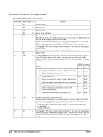
Interface Connector Pin Assignments TM-U200PD printer status and signals Pin number Source 1 Host Compatibility Mode nStrobe Nibble Mode HostClk Byte Mode HostClk 2 Host/Ptr 3 Host/Ptr 4 Host/Ptr Data0(LSB) Data1 Data2 Data0(LSB) Data1 Data2 Data0(LSB) Data1 Data2 5 Host/Ptr Data3 Data3 Data3 6 Host/Ptr 7 Host/Ptr Data4 Data5 Data4 Data5 Data4 Data5 8 Host/Ptr 9 Host/Ptr 10 Printer Data6 Data7(MSB) nAck Data6 Data7(MSB) PtrClk Data6 Data7(MSB) PtrClk 11 Printer Busy PtrBusy/Data3,7 PtrBusy 12 printer 13 Printer PError Select AckDataReq/ Data2,6 Xflag/Data1,5 AckDataReq Xflag 14 Hostr nAutoFd HostBusy HostBusy 15 NC ND ND 16 GND GND GND 17 FG FG FG 18 Printer Logic-H Logic-H Logic-H 19-30 31 Host GND nInit GND nInit GND nInit 32 Printer 33 34 Printer nFault GND DK_STATUS nDataAvail/Data0,4 ND ND nDataAvail ND ND 35 Printer +5V ND ND 36 Host nSelectIn 1284-Active 1284-Active NOTES: t A prefix "n" to signal names refers to "L" active signals. To the host provided with none of the signal lines listed above, both-way communication fails. t For interfacing, signal lines shall use twisted pair cables with the return sides connected to signal ground level. t Interfacing conditions shall be all based on the TTL level to meet the characteristics described below. In addition, both rise time and fall time of each signal shall be 0.5Js or less. t Data transmission shall not ignore the signal nAck or Busy. An attempt to transmit data with either signal, nAck or Busy, ignored can cause lost data. (Data transmissions to the printer shall be made after verifying the nAck signal or while the Busy signal is at the "L" level.) t Interface cables shall be as minimum required short in length as possible. NC: No Connect ND: No Defined 1-20 Features and General Specifications Rev.B
-
 1
1 -
2
-
3
-
4
-
5
-
6
-
7
-
8
-
9
-
10
-
11
-
12
-
13
-
14
-
15
-
16
-
17
-
18
-
19
-
20
-
21
-
22
-
23
-
24
-
25
-
26
-
 27
27 -
 28
28 -
 29
29 -
 30
30 -
 31
31 -
 32
32 -
 33
33 -
 34
34 -
 35
35 -
 36
36 -
 37
37 -
38
-
39
-
40
-
41
-
42
-
43
-
44
-
45
-
46
-
47
-
48
-
49
-
50
-
51
-
52
-
53
-
54
-
55
-
56
-
57
-
58
-
59
-
60
-
61
-
62
-
63
-
64
-
65
-
66
-
67
-
68
-
69
-
70
-
71
-
72
-
73
-
74
-
75
-
76
-
77
-
78
-
79
-
80
-
81
-
82
-
83
-
84
-
85
-
86
-
87
-
88
-
89
-
90
-
91
-
92
-
93
-
94
-
95
-
96
-
97
-
98
-
99
-
100
-
101
-
102
-
103
-
104
-
105
-
106
-
107
-
108
-
109
-
110
-
111
-
112
-
113
-
114
-
115
-
116
-
117
-
118
-
119
-
120
-
121
-
122
-
123
-
124
-
125
-
126
-
127
-
128
-
129
-
130
-
131
-
132
-
133
-
134
-
135
-
136
-
137
-
138
-
139
-
140
-
141
-
142
-
143
-
144
-
145
-
146
-
147
-
148
-
149
-
150
-
151
-
152
-
153
-
154
-
155
-
156
-
157
-
158
-
159
-
160
-
161
-
162
-
163
-
164
-
165
-
166
-
167
-
168
-
169
 |
 |
