Epson TM U200D Technical Reference - Page 28
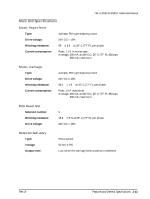
Interface Connector Pin Assignments, TM-U200D printer status and signals - dip switches
 |
View all Epson TM U200D manuals
Add to My Manuals
Save this manual to your list of manuals |
Page 28 highlights
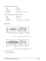
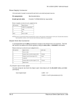
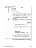
Interface Connector Pin Assignments TM-U200D printer status and signals Pin number Signal name I/O 1 FG - Frame ground Function 2 TXD O Transmit data 3 RXD I Receive data 4 RTS O Same as the DTR signal 6 DSR I This signal indicates whether the host computer can receive data. SPACE indicates that the host computer can receive data, and MARK indicates that the host computer cannot receive data. When DTR/DSR control is selected, the printer transmits data after confirming this signal (except when transmitting data by DLE EOT and GS a). When XON/XOFF control is selected, the printer does not check this signal. Changing the DIP switch setting enables this signal to be used as a reset signal for the printer. The printer is reset when the signal remains MARK for 1 ms or more. 7 SG - Signal ground 20 DTR O 1) When DTR/DSR control is selected, this signal indicates whether the printer is busy. SPACE indicates that the printer is ready to receive data, and MARK indicates that the printer is busy. The busy condition can be changed by using DIP SW 1-8 as follows: Printer DIP SW 1-8 status ON OFF 1. During the period from when the power is turned on (including resetting using the interface) to when the BUSY printer is ready to receive data. BUSY Off-line 2. During the self-test BUSY BUSY 3. During paper feeding using the paper feed button. - BUSY 4. When the printer stops printing due to a paper-end. - BUSY 5. When an error has occurred. - BUSY 6. When a temporary abnormality occurs in the power supply voltage - BUSY 7. When the receive buffer becomes full. (*1) BUSY BUSY 20 DTR O 2) When XON/XOFF control is selected: This signal indicates whether the printer is correctly connected and is ready to receive data. SPACE indicates that the printer is ready to receive data. The signal is always SPACE except in the following cases: t During the period after the power is turned on until the printer is ready to receive data. t During the self test. 25 INIT I Changing the DIP switch setting enables this signal to be used as a reset signal for the printer (see the DIP switch settings in the "Buttons and Switches" section of this chapter). The printer is reset when the signal remains SPACE for 1 ms or more. 1-16 Features and General Specifications Rev.B
-
 1
1 -
2
-
3
-
4
-
5
-
6
-
7
-
8
-
9
-
10
-
11
-
12
-
13
-
14
-
15
-
16
-
17
-
18
-
19
-
20
-
21
-
22
-
 23
23 -
 24
24 -
 25
25 -
 26
26 -
 27
27 -
 28
28 -
 29
29 -
 30
30 -
 31
31 -
 32
32 -
 33
33 -
34
-
35
-
36
-
37
-
38
-
39
-
40
-
41
-
42
-
43
-
44
-
45
-
46
-
47
-
48
-
49
-
50
-
51
-
52
-
53
-
54
-
55
-
56
-
57
-
58
-
59
-
60
-
61
-
62
-
63
-
64
-
65
-
66
-
67
-
68
-
69
-
70
-
71
-
72
-
73
-
74
-
75
-
76
-
77
-
78
-
79
-
80
-
81
-
82
-
83
-
84
-
85
-
86
-
87
-
88
-
89
-
90
-
91
-
92
-
93
-
94
-
95
-
96
-
97
-
98
-
99
-
100
-
101
-
102
-
103
-
104
-
105
-
106
-
107
-
108
-
109
-
110
-
111
-
112
-
113
-
114
-
115
-
116
-
117
-
118
-
119
-
120
-
121
-
122
-
123
-
124
-
125
-
126
-
127
-
128
-
129
-
130
-
131
-
132
-
133
-
134
-
135
-
136
-
137
-
138
-
139
-
140
-
141
-
142
-
143
-
144
-
145
-
146
-
147
-
148
-
149
-
150
-
151
-
152
-
153
-
154
-
155
-
156
-
157
-
158
-
159
-
160
-
161
-
162
-
163
-
164
-
165
-
166
-
167
-
168
-
169
 |
 |
