Fluke 1625 FE 1625 Users Manual - Page 36
Control Loop, Function, Parameter, Setting Range, Remarks
 |
View all Fluke 1625 manuals
Add to My Manuals
Save this manual to your list of manuals |
Page 36 highlights
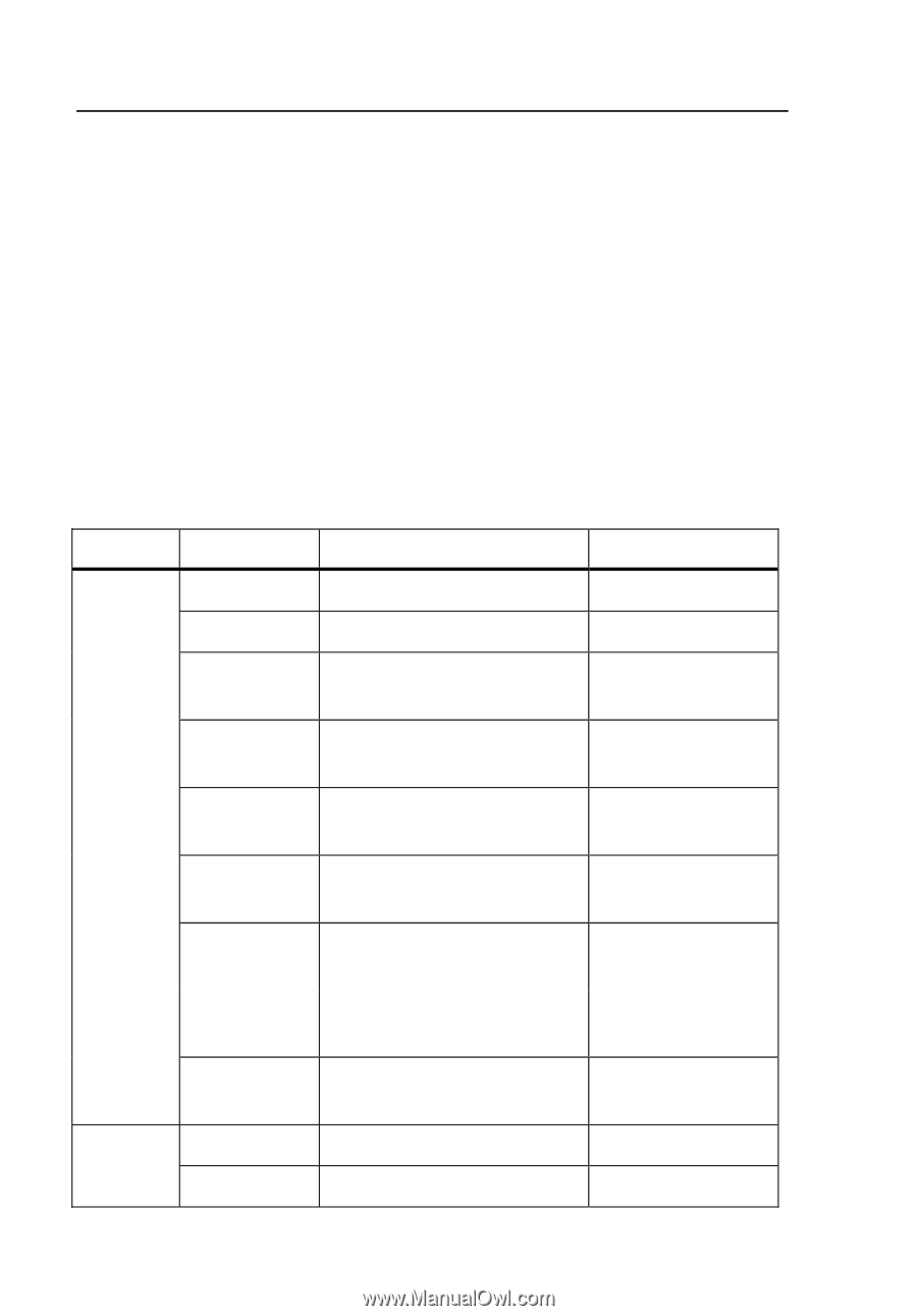
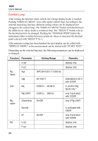
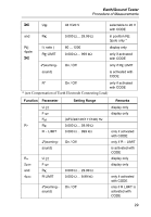
1625 Users Manual Control Loop After turning the function rotary switch, the voltage display mode is reached. Pushing "DISPLAY MENU" now calls up the control loop. According to the selected measuring function, different setting values can be displayed and changed in the control loop. The "DISPLAY MENU" button switches between the different set values inside a contiuous loop. The "SELECT" button selects the decimal point to be changed. Pushing the "CHANGE ITEM" button the instrument either switches between certain set values or increases the decimal point selected with "SELECT" by 1. After parmeter setting has been finished the next display can be called with "DISPLAY MENU" or the measurement can be started with "START TEST". Depending on the selected function, the following parameters can be displayed or changed: Function Parameter Setting Range Remarks RE 3pole and RE 4pole RE U ST F ST FM (AFC/94/105/111/128) Hz display only display only UM 48 V/20 V RK 0.000 Ω ... 29.99 Ω RE LIMIT 0.000 Ω ... 999 kΩ }(warning On/Off selectable to 20 V with CODE in position RE 3pole only * only if activated with CODE only if RE LIMIT Sound) R* U ST F ST On/Off is activated with CODE only if activated with CODE display only display only 28
-
 1
1 -
2
-
3
-
4
-
5
-
6
-
7
-
8
-
9
-
10
-
11
-
12
-
13
-
14
-
15
-
16
-
17
-
18
-
19
-
20
-
21
-
22
-
23
-
24
-
25
-
26
-
27
-
28
-
29
-
30
-
 31
31 -
 32
32 -
 33
33 -
 34
34 -
 35
35 -
 36
36 -
 37
37 -
 38
38 -
 39
39 -
 40
40 -
 41
41 -
42
-
43
-
44
-
45
-
46
-
47
-
48
-
49
-
50
-
51
-
52
-
53
-
54
-
55
-
56
-
57
-
58
-
59
-
60
-
61
-
62
-
63
-
64
-
65
-
66
-
67
-
68
-
69
-
70
-
71
-
72
-
73
-
74
-
75
-
76
-
77
-
78
-
79
-
80
-
81
-
82
-
83
-
84
-
85
-
86
-
87
-
88
-
89
-
90
 |
 |