Fluke 1625 FE 1625 Users Manual - Page 42
Remarks for the setting of earth spikes
 |
View all Fluke 1625 manuals
Add to My Manuals
Save this manual to your list of manuals |
Page 42 highlights
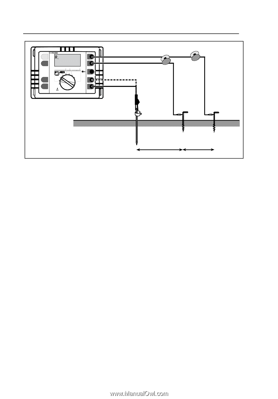
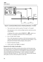
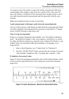
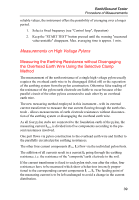
1625 Users Manual START TEST 1625 EARTH / GROUND TESTER H /C2 DISPLAY MENU Earth/Ground Resistance 300 k RA CHANGE ITEM 4 POLE 3 POLE 4 POLE 3 POLE AC Resistance 300 k R DC Low Resistance 3k R 2 POLE 2 POLE 4 POLE SELECT OFF S/P2 ES/P1 E /C1 4 pole Earth electrode Probe Auxiliary earth electrode >20 m >20 m edw012.eps Figure 9. 3-pole/4-pole Measurement of Earthing Resistance - Process 1. Turn central rotary switch to position "RE 3pole" or "RE 4pole" The instrument is to be wired according to picture and notices given on the display. A flashing of the sockets symbols EFGH or A, points to an incorrect or incomplete connection of the measuring lead. 2. Press "START TEST" button Now a fully automated test sequence of all relevant parameters like auxiliary earth electrode, probe- and earth electrode resistance, is implemented and finished with the display of the result RE. 3. Read out measured value RE 4. Call RS and RH with "DISPLAY MENU". Remarks for the setting of earth spikes: Before setting the earth spikes for probe and auxiliary earth electrode make sure that the probe is set outside the potential gradient area of earth electrode and auxiliary earth electrode (also see "The Influence of Potential Gradient areas on Earth Resistance Measurement"). Such a condition is normally reached by allowing a distance of > 20 m between the earth electrode and the earth spikes as well as of the earth spikes to each other. 34
-
 1
1 -
2
-
3
-
4
-
5
-
6
-
7
-
8
-
9
-
10
-
11
-
12
-
13
-
14
-
15
-
16
-
17
-
18
-
19
-
20
-
21
-
22
-
23
-
24
-
25
-
26
-
27
-
28
-
29
-
30
-
31
-
32
-
33
-
34
-
35
-
36
-
 37
37 -
 38
38 -
 39
39 -
 40
40 -
 41
41 -
 42
42 -
 43
43 -
 44
44 -
 45
45 -
 46
46 -
 47
47 -
48
-
49
-
50
-
51
-
52
-
53
-
54
-
55
-
56
-
57
-
58
-
59
-
60
-
61
-
62
-
63
-
64
-
65
-
66
-
67
-
68
-
69
-
70
-
71
-
72
-
73
-
74
-
75
-
76
-
77
-
78
-
79
-
80
-
81
-
82
-
83
-
84
-
85
-
86
-
87
-
88
-
89
-
90
 |
 |