Fluke 1625 FE 1625 Users Manual - Page 88
The Influence of Potential Gradient Areas on Earth Resistance Measurement
 |
View all Fluke 1625 manuals
Add to My Manuals
Save this manual to your list of manuals |
Page 88 highlights
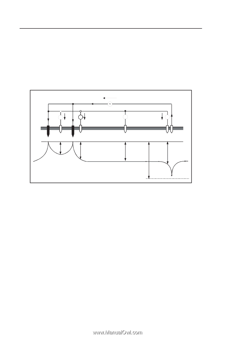
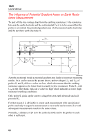
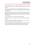
1625 Users Manual The Influence of Potential Gradient Areas on Earth Resistance Measurement To pick off the true voltage drop from the earthing resistance (= the resistance between the earth electrode and the soil potential FE) it is to be assured that the probe is set outside the potential gradient area of all connected earth electrodes and the auxiliary earth electrode H. I I1 US1 V V US2 I2 E1 S1 E2 S2 UG G US2 V S3 I US4 V S4 H US1 US2 US3 FE US4 UG edw059.eps A probe positioned inside a potential gradient area leads to incorrect measuring results. As it can be seen in the picture above, probe voltages US1 and US2 of probes S1 and S2 deliver a value too low, which also means that the earthing resistance appears to be lower than it actually is(low resistance). Probe S 4 with US4 on the other hand, picks up a value too high which indicates a worse (high resistance) earthing conditions. Only probe S3 picks up the correct voltage between earth electrode and soil potential FE. For that reason it is advisable to repeat each measurement with repositioned probes and only to regard a measurement as successful and accurate if several subsequent measurements result in the same values. Normally, a distance of 20 m to the earth electrode and to the probes to each other is sufficient. 80
-
 1
1 -
2
-
3
-
4
-
5
-
6
-
7
-
8
-
9
-
10
-
11
-
12
-
13
-
14
-
15
-
16
-
17
-
18
-
19
-
20
-
21
-
22
-
23
-
24
-
25
-
26
-
27
-
28
-
29
-
30
-
31
-
32
-
33
-
34
-
35
-
36
-
37
-
38
-
39
-
40
-
41
-
42
-
43
-
44
-
45
-
46
-
47
-
48
-
49
-
50
-
51
-
52
-
53
-
54
-
55
-
56
-
57
-
58
-
59
-
60
-
61
-
62
-
63
-
64
-
65
-
66
-
67
-
68
-
69
-
70
-
71
-
72
-
73
-
74
-
75
-
76
-
77
-
78
-
79
-
80
-
81
-
82
-
 83
83 -
 84
84 -
 85
85 -
 86
86 -
 87
87 -
 88
88 -
 89
89 -
 90
90
 |
 |