Fluke 1625 FE 1625 Users Manual - Page 9
Earth/Ground Tester, Introduction - earth ground tester
 |
View all Fluke 1625 manuals
Add to My Manuals
Save this manual to your list of manuals |
Page 9 highlights
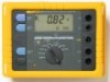
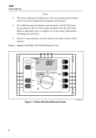
Earth/Ground Tester Introduction At locations involving the generation, distribution and consumption of electrical energy, certain safety measures must be met in order to protect human life. In many cases, these safety measures are national and international regulations which must be checked regularly. Grounding, the connection of exposed conductive parts to the earth in case of a fault, represents the most fundamental safety measure. There are requirements for grounding of transformers, high and medium voltage power pylons, railway tracks, tanks, vats, foundations and lightning protection systems. The effectiveness of grounding systems should be checked using a ground test instruments such as the 1625 which checks the effectiveness of connections to the ground. The 1625 provides the perfect solution by combining the latest technology into a compact, field-rugged and extremely easy to use instrument. In addition to performing standard 3- and 4-pole ground resistance measurements, an innovative process accurately measures individual earth electrode resistances in single and meshed earthed systems without disconnecting any parallel electrodes. One specific application of this capability is quick and accurate measurement of power pylon grounds. The 1625 also incorporates automatic frequency control (AFC) to minimize interference. Before measuring, the instrument identifies existing interference and selects a measurement frequency to minimise its effect. The 1625 incorporates microprocessor controlled automatic measurements including checking probe hookup to ensure that measurements are taken correctly. It measures all probe ground resistances to ensure reliable, repeatable results. Probe resistance and auxiliary earth resistance are also measured and displayed. 1
-
 1
1 -
2
-
3
-
 4
4 -
 5
5 -
 6
6 -
 7
7 -
 8
8 -
 9
9 -
 10
10 -
 11
11 -
 12
12 -
 13
13 -
 14
14 -
15
-
16
-
17
-
18
-
19
-
20
-
21
-
22
-
23
-
24
-
25
-
26
-
27
-
28
-
29
-
30
-
31
-
32
-
33
-
34
-
35
-
36
-
37
-
38
-
39
-
40
-
41
-
42
-
43
-
44
-
45
-
46
-
47
-
48
-
49
-
50
-
51
-
52
-
53
-
54
-
55
-
56
-
57
-
58
-
59
-
60
-
61
-
62
-
63
-
64
-
65
-
66
-
67
-
68
-
69
-
70
-
71
-
72
-
73
-
74
-
75
-
76
-
77
-
78
-
79
-
80
-
81
-
82
-
83
-
84
-
85
-
86
-
87
-
88
-
89
-
90
 |
 |