Honeywell Heat/1Cool User Guide - Page 15
Understanding Circuits - heat cool thermostats
 |
View all Honeywell Heat/1Cool manuals
Add to My Manuals
Save this manual to your list of manuals |
Page 15 highlights
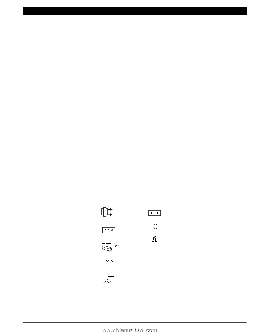
HEAT PUMP THERMOSTAT CROSS REFERENCE/SELECTION GUIDE Understanding Circuits To understand wiring diagrams, it is important to know what all the symbols mean and how to trace the path of the circuits from the transformer. Circuit descriptions and terminology are defined as follows: Auto changeover-refers to the presence of an AUTO position in the system switching (EX: Q674F with OFF-COOL AUTO-HEAT-EM. HEAT switching). The thermostat automatically changes between heat and cool modes as indoor temperature changes. Manual changeover-requires a system switch movement to change mode (EX: Q674L with EM. HT.-HEAT-OFFCOOL switching). Cool changeover valve-operates on cooling. The reversing valve or relay is activated either by moving the system switch to COOL (manual changeover) or by a mercury switch that makes on a temperature rise (auto changeover). Heat changeover valve-operates on heating. The reversing valve or relay is activated either by moving the system switch to HEAT (manual changeover) or by a mercury switch that makes on a temperature fall (auto changeover). System monitor relay-optional equipment on some heat pumps. This system monitor relay detects a malfunction in the compressor and indicates the malfunction by activating the EMERGENCY HEAT LED on the switching subbase. The system monitor relay may be wired to the L terminal on some thermostats Each mercury switch is identified by function: H1-Stage 1 Heating. H2-Stage 2 Heating. H3-Stage 3 Heating. C1-Stage 1 Cooling. C2-Stage 2 Cooling. C3-Stage 3 Cooling. C/O-Changeover (heat pumps). Each anticipator is identified and each switch affected is named (EX: H1 anticipator, C1 anticipator). All T874 Multistage Thermostats use mercury switches. Each schematic indicates switch operation by being drawn in the open position with an arrow indicating operation with a temperature RISE or FALL. KEY TO HOOKUP SYMBOLS TRANSFORMER (24 VAC SECONDARY) RELAY OR CONTACTOR COIL RELAY/CONTACTOR CONTACTS B TERMINAL LED MERCURY SWITCH FIXED ANTICIPATOR HIGH RESISTANCE (TYPICALLY 5 KILOHMS) ADJUSTABLE ANTICIPATOR LOW RESISTANCE (TYPICALLY 0 TO 5 OHMS) ODT OUTDOOR THERMOSTAT EHR EMERGENCY HEAT RELAY RTD TIME DELAY RELAY RD DEFROST RELAY CHP PRESSURE SWITCH LACO LOW AMBIENT CUTOFF M5848 Fig. 14. Key to hookup symbols. 70-6627 • 13
-
 1
1 -
2
-
3
-
4
-
5
-
6
-
7
-
8
-
9
-
 10
10 -
 11
11 -
 12
12 -
 13
13 -
 14
14 -
 15
15 -
 16
16 -
 17
17 -
 18
18 -
 19
19 -
 20
20 -
21
-
22
-
23
-
24
-
25
-
26
-
27
-
28
-
29
-
30
-
31
-
32
-
33
-
34
-
35
-
36
-
37
-
38
-
39
-
40
-
41
-
42
-
43
-
44
-
45
-
46
-
47
-
48
-
49
-
50
-
51
-
52
-
53
-
54
-
55
-
56
-
57
-
58
-
59
-
60
-
61
-
62
-
63
-
64
-
65
-
66
-
67
-
68
-
69
-
70
-
71
-
72
-
73
-
74
-
75
-
76
-
77
-
78
-
79
-
80
-
81
-
82
-
83
-
84
-
85
-
86
-
87
-
88
-
89
-
90
-
91
-
92
-
93
-
94
-
95
-
96
-
97
-
98
-
99
-
100
-
101
-
102
-
103
-
104
-
105
-
106
-
107
-
108
-
109
-
110
-
111
-
112
-
113
-
114
-
115
-
116
-
117
-
118
-
119
-
120
-
121
-
122
-
123
-
124
 |
 |