Honeywell Heat/1Cool User Guide - Page 57
Florida Heat Pump - heat cool units
 |
View all Honeywell Heat/1Cool manuals
Add to My Manuals
Save this manual to your list of manuals |
Page 57 highlights
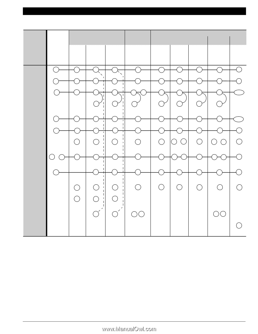
Electromechanical Chronotherm® III FLORIDA HEAT PUMP TYPICAL "LT" UNITS Electronic Replacement or Upgrade Chronotherm IV T841A1712 Y594R1425 Y5Y9549G41G4174619 T8T681611G11R0100400 T8T481411R11R0120802 T8T581511G11G0140721 T8T081011R11R0110406 T8T681611G12G0220802 W890P0CB8190000/2 Function Existing Terminals Common ´ C X X X C C C C C C Power R Compressor Y 1st Stage - Heat Aux. Heat W R R R R R R R R R or Y Y Y1 Y1 Y Y Y1 Y Y1 Y1/W1 ² ² ² ² ² ² ² - W1 W1 W1 W1 W1 W1 W1 - µ W2 W2 W2 W2 W2 W2 W2 W2 Aux. Fan G C/O Valve - Heat C/O Valve or W O Cool System Monitor/ X System Defrost EM. Heat - G G G B B B O E¿ O · L ¿ E O · X1 E¿ G B O ¾ L E¿ G G ³ or B B O/B ³ or O O O/B ¾ · L L ¿ ¿ E E G G ³ or B B O/B ³ or O O O/B ¾ · L L ¿ ¿ E E G ³ O/B ³ O/B · L ¿ E Multiple Aux. - W3 W3 W3 - Heat Loads » - - - - - LED Indication - 2nd Stage - Compressor - X2 º X2 º X1 X2 ¶ - - - - - - - - - X1 X2 - - - W2 µ ³ Configure O/B (select models) in Installer Setup. · LED is energized when terminal is powered. » Terminal is for multiple second stage heating loads such as contactors, sequencers, or relays. ¿ E-W2 jumper required unless emergency heat function is wired separately. ´ Terminal X (C) must be connected to transformer common. ² Do not remove factory-installed jumper. ¶ Optional CHECK LED on T8611G1004. See Fig. 26. º Field-installed X2 to X jumper (provided). ¾ L terminal is powered continuously when thermostat is in Em. Ht. position. µ When W2 is not used, configure W2 cycle rate to NC. M13175 70-6627 • 55
-
 1
1 -
2
-
3
-
4
-
5
-
6
-
7
-
8
-
9
-
10
-
11
-
12
-
13
-
14
-
15
-
16
-
17
-
18
-
19
-
20
-
21
-
22
-
23
-
24
-
25
-
26
-
27
-
28
-
29
-
30
-
31
-
32
-
33
-
34
-
35
-
36
-
37
-
38
-
39
-
40
-
41
-
42
-
43
-
44
-
45
-
46
-
47
-
48
-
49
-
50
-
51
-
 52
52 -
 53
53 -
 54
54 -
 55
55 -
 56
56 -
 57
57 -
 58
58 -
 59
59 -
 60
60 -
 61
61 -
 62
62 -
63
-
64
-
65
-
66
-
67
-
68
-
69
-
70
-
71
-
72
-
73
-
74
-
75
-
76
-
77
-
78
-
79
-
80
-
81
-
82
-
83
-
84
-
85
-
86
-
87
-
88
-
89
-
90
-
91
-
92
-
93
-
94
-
95
-
96
-
97
-
98
-
99
-
100
-
101
-
102
-
103
-
104
-
105
-
106
-
107
-
108
-
109
-
110
-
111
-
112
-
113
-
114
-
115
-
116
-
117
-
118
-
119
-
120
-
121
-
122
-
123
-
124
 |
 |