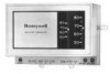
Honeywell Heat/1Cool User Guide - Page 37
Con O/B Select Models in Installer Setup.
 |
View all Honeywell Heat/1Cool manuals
Add to My Manuals
Save this manual to your list of manuals |
Page 37 highlights
HEAT PUMP THERMOSTAT CROSS REFERENCE/SELECTION GUIDE ³ Terminal must be connected to the transformer common. · Terminal is for multiple auxiliary heat loads such as contactors, sequencers, or relays. » Configure O/B (Select Models) in Installer Setup. ¿ Optional LED indication activated with completed circuit on X1 and X2 terminals. ´ If separate Y1 and W1 terminals are required, install R8222D1014; (See page 12.) ² When W2 is not used, configure W2 cycle rate to NC. ¶ LED is energized when terminal is powered. º L terminal is powered continuously when thermostat is in Em. Ht. position. ¾ Do not remove factory-installed jumper. µ If multiple auxiliary heat loads are used, connect to W2 (Aux W8900B) terminal. ¸ Used on two-speed compressor heat pump applications. ¹ Used on heat pumps that energize the compressor on both first stage cooling and first stage heating through a common Y terminal. Ƹ Q674F1022 switching subbase available when separate first stage heat and cool terminals are required. See specific heat pump manufacturer's listing for hookup information. ƹ P terminal on T8611R1000 only. Energized in heating and cooling modes; shown only when used. ƺ Jumper W2 and Y2 if stage 2 heating and cooling are common. ƻ To change fan operation in Emergency Heat mode, see page 9. X1 TO R CHECK LED FAULT DETECTION SWITCH (YELLOW) X2 TO C/X SWITCH TO R (POWER) SIDE OF SYSTEM TRANSFORMER X1 TO R X1 CHECK LED (YELLOW) FAULT DETECTION SWITCH X2 TO C/X CHECK LED SWITCHING DEVICE (YELLOW) 24 VAC X2 SWITCH TO C (COMMON) SIDE OF SYSTEM TRANSFORMER SWITCH IN SECONDARY OF SEPARATE TRANSFORMER L1 (HOT) L2 M13246 70-6627 • 35
-
 1
1 -
2
-
3
-
4
-
5
-
6
-
7
-
8
-
9
-
10
-
11
-
12
-
13
-
14
-
15
-
16
-
17
-
18
-
19
-
20
-
21
-
22
-
23
-
24
-
25
-
26
-
27
-
28
-
29
-
30
-
31
-
 32
32 -
 33
33 -
 34
34 -
 35
35 -
 36
36 -
 37
37 -
 38
38 -
 39
39 -
 40
40 -
 41
41 -
 42
42 -
43
-
44
-
45
-
46
-
47
-
48
-
49
-
50
-
51
-
52
-
53
-
54
-
55
-
56
-
57
-
58
-
59
-
60
-
61
-
62
-
63
-
64
-
65
-
66
-
67
-
68
-
69
-
70
-
71
-
72
-
73
-
74
-
75
-
76
-
77
-
78
-
79
-
80
-
81
-
82
-
83
-
84
-
85
-
86
-
87
-
88
-
89
-
90
-
91
-
92
-
93
-
94
-
95
-
96
-
97
-
98
-
99
-
100
-
101
-
102
-
103
-
104
-
105
-
106
-
107
-
108
-
109
-
110
-
111
-
112
-
113
-
114
-
115
-
116
-
117
-
118
-
119
-
120
-
121
-
122
-
123
-
124
 |
 |
