Honeywell Heat/1Cool User Guide - Page 46
Function, Electromechanical, Chronotherm, Electronic Replacement or Upgrade, Chronotherm IV
 |
View all Honeywell Heat/1Cool manuals
Add to My Manuals
Save this manual to your list of manuals |
Page 46 highlights
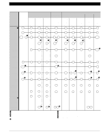
CARRIER USES HONEYWELL Q674L1116 (HH93AZ171) SUBBASE Electromechanical Chronotherm® III Electronic Replacement or Upgrade Chronotherm IV AVAILNAOBTLE AVAILNAOBTLE Q67T487F410D21216º5/ T8611M7008 T8511M1002 TT88661111MM22002157 W890P0CB8190000/2 Function Common · Existing Terminals C X1 C C C C Power R ¶ Compressor Y R R R R R ¶ ¶ Y1 Y Y1 Y1 Y1/W1 1st Stg. Heat 2nd Stage Compressor - ´ Y1 W1 - - - - W2 W2 Y2 Y2 W2 NOT AVAILABLE NOT AVAILABLE Fan G C/O Valve - Heat C/O Valve O Cool System Monitor/ L System Defrost EM. Heat E 2nd Stg. Cool - LED Indication - G G B B O ² X2 ² E Y2 ³ - O µ L E Y2 ³ X1 X2 » G ¿ O/B ¿ O/B ¾ L E - - G ¿ O/B ¿ O/B µ L E - X2 » G ¿ O/B ¿ O/B ¾ L E Y2 ³ - ³ Jumper Y2 to W2. · Terminal C (X1) must be connected to transformer common. » Optional CHECK LED on T8611M7008. Connect L to X1, jumper X2 to C. ¿ Configure O/B (select models) in Installer Setup. ´ In this application, auxiliary heat and compressor two are both connected to terminal Y1. ² For second stage compressor LED indication, jumper X2 to Y2 on Q674. For emergency heat LED indication, jumper X2 to E. For system monitor LED indication, connect L to X2. ¶ Both first stage heat and cool are connected to Y or Y1/W1 terminal. º When subbase system switch is in AUTO position, equipment operates in cool mode only. ¾ LED is energized when terminal is powered. µ L terminal is powered continuously when thermostat is in Em. Ht. position. M13149 TYPICAL THERMOSTATS AND SUBBASES - HONEYWELL MODEL NUMBER (CUSTOMER PART NUMBER) T874D1264/Q674L1116 (HH07AT173/HH93AZ171) 70-6627 • 44
-
 1
1 -
2
-
3
-
4
-
5
-
6
-
7
-
8
-
9
-
10
-
11
-
12
-
13
-
14
-
15
-
16
-
17
-
18
-
19
-
20
-
21
-
22
-
23
-
24
-
25
-
26
-
27
-
28
-
29
-
30
-
31
-
32
-
33
-
34
-
35
-
36
-
37
-
38
-
39
-
40
-
 41
41 -
 42
42 -
 43
43 -
 44
44 -
 45
45 -
 46
46 -
 47
47 -
 48
48 -
 49
49 -
 50
50 -
 51
51 -
52
-
53
-
54
-
55
-
56
-
57
-
58
-
59
-
60
-
61
-
62
-
63
-
64
-
65
-
66
-
67
-
68
-
69
-
70
-
71
-
72
-
73
-
74
-
75
-
76
-
77
-
78
-
79
-
80
-
81
-
82
-
83
-
84
-
85
-
86
-
87
-
88
-
89
-
90
-
91
-
92
-
93
-
94
-
95
-
96
-
97
-
98
-
99
-
100
-
101
-
102
-
103
-
104
-
105
-
106
-
107
-
108
-
109
-
110
-
111
-
112
-
113
-
114
-
115
-
116
-
117
-
118
-
119
-
120
-
121
-
122
-
123
-
124
 |
 |
