Honeywell Heat/1Cool User Guide - Page 81
Existing, Terminals, PC8900, T874D1165
 |
View all Honeywell Heat/1Cool manuals
Add to My Manuals
Save this manual to your list of manuals |
Page 81 highlights
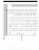
LENNOX HP11 IMPORTANT: Replace separate indoor/outdoor transformers with single 75 VA transformer. See diagram on page 78. Electromechanical Chronotherm® III Electronic Replacement or Upgrade Chronotherm IV Q6T78474F1D0121265/ T8611M7008 T8511M1002 T8T6816111M2M0220517 W89P00C8B910000/2 Existing ³ Function Terminals Common ¿ X X1 C C C C ¶ Power Indoor VR R R R R R Common Outside X - - - - - ¶ Common Outside V ¶ ¶ ¶ ¶ ¶ Compressor Stage 1 M ´ Y1 Y Y1 Y1 Y1/W1 Compressor Stage 2 M2 Y2 Y2 Y2 Y2 Y2 Auxiliary Heat Y W2 W2 » W3 - » W3 - » W3 W2 Aux. » Fan F C/O Valve R Cool C/O Valve - Heat System Monitor/ L System Defrost G O B · X2 G O B µ L G º O/B º O/B ¾ L G º O/B O/B º µ L G º O/B º O/B ¾ L Em. Heat E E E E E E Thermistor A - - - - - 1st Stage Heat - W1 - - - - LED Indication - - ² X1 X2 - X1 X2 ² - ³ IMPORTANT: When subbase system is in AUTO position, equipment will operate in COOL mode only (Q674F1022). · For emergency heat indication, jumper E and X2. For auxiliary heat indication, jumper W2 and X2. For any X2 functions, X1 must be connected to transformer common. » For proper operation of auxiliary heat connect Y to W3 or AUX terminal. ¿ Terminal must be connected to the transformer common. ´ W1 to Y1 jumper required. ² Optional LED indication activated with completed circuit on X1 and X2 terminals. ¶ Replace separate indoor and outdoor transformers with one 75 VA transformer. See page 78 for wiring diagram. º Configure O/B (select models) in Installer Setup. ¾ LED is energized when terminal is powered. µ L terminal is powered continuously when thermostat is in Em. Ht. position. M13156 TYPICAL THERMOSTATS AND SUBBASES - HONEYWELL MODEL NUMBER T872G1323/Q672L1201 T874D1033 T874D1199 T874D1207/Q674L1199 T874D1207/Q674L1389 70-6627 • 79
-
 1
1 -
2
-
3
-
4
-
5
-
6
-
7
-
8
-
9
-
10
-
11
-
12
-
13
-
14
-
15
-
16
-
17
-
18
-
19
-
20
-
21
-
22
-
23
-
24
-
25
-
26
-
27
-
28
-
29
-
30
-
31
-
32
-
33
-
34
-
35
-
36
-
37
-
38
-
39
-
40
-
41
-
42
-
43
-
44
-
45
-
46
-
47
-
48
-
49
-
50
-
51
-
52
-
53
-
54
-
55
-
56
-
57
-
58
-
59
-
60
-
61
-
62
-
63
-
64
-
65
-
66
-
67
-
68
-
69
-
70
-
71
-
72
-
73
-
74
-
75
-
 76
76 -
 77
77 -
 78
78 -
 79
79 -
 80
80 -
 81
81 -
 82
82 -
 83
83 -
 84
84 -
 85
85 -
 86
86 -
87
-
88
-
89
-
90
-
91
-
92
-
93
-
94
-
95
-
96
-
97
-
98
-
99
-
100
-
101
-
102
-
103
-
104
-
105
-
106
-
107
-
108
-
109
-
110
-
111
-
112
-
113
-
114
-
115
-
116
-
117
-
118
-
119
-
120
-
121
-
122
-
123
-
124
 |
 |
