Honeywell Heat/1Cool User Guide - Page 85
Magic Chef
 |
View all Honeywell Heat/1Cool manuals
Add to My Manuals
Save this manual to your list of manuals |
Page 85 highlights
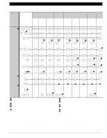
Electromechanical Chronotherm® III MAGIC CHEF "PB" SERIES EQUIPMENT Electronic Replacement or Upgrade Chronotherm IV AVAILNAOBTLE Q6T78³474B1C0130418/ Y5Y9549G41G4174619 T8611R1000 T8T481411R11R0120802 T8T581511G11G0140721 T8T081011R11R0110406 T8T681611G12G0220802 W890P0CB8190000/2 Existing Function Terminals Common · C X C C C C C C Power R 1st Stage Y1 Cool 1st Stage W1 Heat Rc R Y1 Y1 » » W1 W1 R Y1 » W1 R Y » W1 R Y1 » W1 R Y » W1 R Y1 » W1 R ² Y1/W1 - NOT AVAILABLE 2nd Stage W2 Heat W2 W2 W2 W2 W2 W2 W2 W2 Fan G C/O Valve - Heat C/O Valve O Cool System Monitor/ X1 System Defrost G G G G G G G G B B B B B or O/B B B or O/B O/B O O O O O or O/B O O or O/B O/B ´ X1 ᕤ L ᕤ ´ L L ᕤ L ´ L ´ L EM. Heat E - E E E E E E E 2nd Stage - Cool Y2 - - - - - - Y2 Power Heat - Rh - - - - - - - ³ IMPORTANT: No provision for emergency heat, system monitor (compressor fault), or auxiliary heat LEDs. · Terminal C (X) must be connected to transformer common. » Remove Y1 (Y) to W1 (W) jumper. ¿ L terminal is powered continuously when thermostat is in Em. Ht. position. ´ LED is energized when terminal is powered. ² If separate Y1 and W1 terminals required, install R8222D1014; see page 12. M13167 70-6627 • 83
-
 1
1 -
2
-
3
-
4
-
5
-
6
-
7
-
8
-
9
-
10
-
11
-
12
-
13
-
14
-
15
-
16
-
17
-
18
-
19
-
20
-
21
-
22
-
23
-
24
-
25
-
26
-
27
-
28
-
29
-
30
-
31
-
32
-
33
-
34
-
35
-
36
-
37
-
38
-
39
-
40
-
41
-
42
-
43
-
44
-
45
-
46
-
47
-
48
-
49
-
50
-
51
-
52
-
53
-
54
-
55
-
56
-
57
-
58
-
59
-
60
-
61
-
62
-
63
-
64
-
65
-
66
-
67
-
68
-
69
-
70
-
71
-
72
-
73
-
74
-
75
-
76
-
77
-
78
-
79
-
 80
80 -
 81
81 -
 82
82 -
 83
83 -
 84
84 -
 85
85 -
 86
86 -
 87
87 -
 88
88 -
 89
89 -
 90
90 -
91
-
92
-
93
-
94
-
95
-
96
-
97
-
98
-
99
-
100
-
101
-
102
-
103
-
104
-
105
-
106
-
107
-
108
-
109
-
110
-
111
-
112
-
113
-
114
-
115
-
116
-
117
-
118
-
119
-
120
-
121
-
122
-
123
-
124
 |
 |
