IBM 8479 User Reference - Page 55
result in exposure to hazardous laser radiation. There are no serviceable
 |
UPC - 087944653912
View all IBM 8479 manuals
Add to My Manuals
Save this manual to your list of manuals |
Page 55 highlights
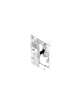
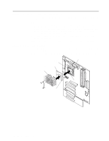
Attention: When you handle static-sensitive devices, take precautions to avoid damage from static electricity. For details on handling these devices, see "Handling static-sensitive devices" on page 27. 1. Read the information in "Preinstallation steps (all bays)" on page 40 and "Safety information" on page 28. 2. Turn off the server and peripheral devices and disconnect the external cables and power cords; then, remove the side cover (see "Removing the side cover" on page 33 for details). 3. Remove the support-bracket assembly and disconnect the fan cable from the connector (SYSFA3) on the system board. See "Removing the support-bracket assembly" on page 34 for details. See "System board internal cable connectors" on page 24 for the location of the fan cable connector. 4. Use a screwdriver to gently pry the filler panel and EMC shield away from the server. Note: If you are installing a drive that is a laser product, observe the following safety precaution. Statement 3 CAUTION: When laser products (such as CD-ROMs, DVD drives, fiber optic devices, or transmitters) are installed, note the following: • Do not remove the covers. Removing the covers of the laser product could result in exposure to hazardous laser radiation. There are no serviceable parts inside the device. • Use of controls or adjustments or performance of procedures other than those specified herein might result in hazardous radiation exposure. Danger Some laser products contain an embedded Class 3A or Class 3B laser diode. Note the following. Laser radiation when open. Do not stare into the beam, do not view directly with optical instruments, and avoid direct exposure to the beam. 5. Touch the static-protective package containing the drive to any unpainted metal surface on the server; then, remove the drive from the package and place it on a static-protective surface. 6. Set any jumpers or switches on the drive according to the documentation that comes with the drive. 7. Install the drive: • If you are installing a 5.25-in. drive in bay 2, push the drive into the bay. Then, use the two screws that come with your option to attach the drive to the drive cage. • If you are installing a 3.5-in. drive in bay 2, you must attach the 5.25-in. conversion kit, supplied with your option, to the 3.5-in. drive. 8. Cable the drive: Chapter 5. Installing options 41
-
 1
1 -
2
-
3
-
4
-
5
-
6
-
7
-
8
-
9
-
10
-
11
-
12
-
13
-
14
-
15
-
16
-
17
-
18
-
19
-
20
-
21
-
22
-
23
-
24
-
25
-
26
-
27
-
28
-
29
-
30
-
31
-
32
-
33
-
34
-
35
-
36
-
37
-
38
-
39
-
40
-
41
-
42
-
43
-
44
-
45
-
46
-
47
-
48
-
49
-
 50
50 -
 51
51 -
 52
52 -
 53
53 -
 54
54 -
 55
55 -
 56
56 -
 57
57 -
 58
58 -
 59
59 -
 60
60 -
61
-
62
-
63
-
64
-
65
-
66
-
67
-
68
-
69
-
70
-
71
-
72
-
73
-
74
-
75
-
76
-
77
-
78
-
79
-
80
-
81
-
82
-
83
-
84
-
85
-
86
-
87
-
88
-
89
-
90
-
91
-
92
-
93
-
94
-
95
-
96
-
97
-
98
-
99
-
100
-
101
-
102
-
103
-
104
-
105
-
106
-
107
-
108
-
109
-
110
-
111
-
112
-
113
-
114
-
115
-
116
-
117
-
118
-
119
-
120
-
121
-
122
-
123
-
124
-
125
-
126
-
127
-
128
 |
 |
