IBM 8479 User Reference - Page 58
Your xSeries 200 server supports 128 MB, 256 MB, and 512 MB DIMMs. Your, Save Settings, Attention
 |
UPC - 087944653912
View all IBM 8479 manuals
Add to My Manuals
Save this manual to your list of manuals |
Page 58 highlights
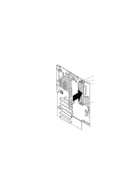
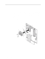
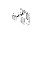
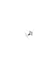
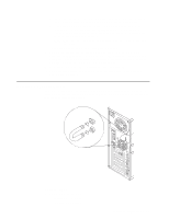
Memory considerations: • Your server comes with a DIMM installed on the system board in DIMM connector 1. When installing additional memory modules, install the second memory module in DIMM connector 2, and the third in DIMM connector 3. (See the illustration in this section for memory connector locations.) • Your xSeries 200 server supports 128 MB, 256 MB, and 512 MB DIMMs. Your server supports a minimum of 128 MB and a maximum of 1.5 GB of system memory. See the ServerProven list at http://www.ibm.com/pc/compat for a list of memory modules for use with your server. • Installing or removing DIMMs changes the configuration information in the server. Therefore, after installing or removing a DIMM, you must change and save the new configuration information by using the Configuration/Setup Utility program. When you restart the server, the system displays a message indicating that the memory configuration has changed. Start the Configuration/Setup Utility program and select Save Settings. See Chapter 3, "Configuring your server," on page 9 for more information. • The illustrations in this document might differ slightly from your hardware. DIMM connector 1 DIMM connector 2 DIMM connector 3 Retaining clip Complete the following steps to install a DIMM. Attention: When you handle static-sensitive devices, take precautions to avoid damage from static electricity. For details on handling these devices, see "Handling static-sensitive devices" on page 27. 1. Review the safety precautions in Statement 1 and Statement 5 in "Safety information" on page 28. 2. Turn off the server and peripheral devices and disconnect all external cables and power cords; then, remove the cover (see "Removing the side cover" on page 33 for details). 3. Remove the support-bracket assembly and disconnect the fan cable from the connector (SYSFA3) on the system board. See "Removing the support-bracket 44 IBM xSeries 200: User's Reference
-
 1
1 -
2
-
3
-
4
-
5
-
6
-
7
-
8
-
9
-
10
-
11
-
12
-
13
-
14
-
15
-
16
-
17
-
18
-
19
-
20
-
21
-
22
-
23
-
24
-
25
-
26
-
27
-
28
-
29
-
30
-
31
-
32
-
33
-
34
-
35
-
36
-
37
-
38
-
39
-
40
-
41
-
42
-
43
-
44
-
45
-
46
-
47
-
48
-
49
-
50
-
51
-
52
-
 53
53 -
 54
54 -
 55
55 -
 56
56 -
 57
57 -
 58
58 -
 59
59 -
 60
60 -
 61
61 -
 62
62 -
 63
63 -
64
-
65
-
66
-
67
-
68
-
69
-
70
-
71
-
72
-
73
-
74
-
75
-
76
-
77
-
78
-
79
-
80
-
81
-
82
-
83
-
84
-
85
-
86
-
87
-
88
-
89
-
90
-
91
-
92
-
93
-
94
-
95
-
96
-
97
-
98
-
99
-
100
-
101
-
102
-
103
-
104
-
105
-
106
-
107
-
108
-
109
-
110
-
111
-
112
-
113
-
114
-
115
-
116
-
117
-
118
-
119
-
120
-
121
-
122
-
123
-
124
-
125
-
126
-
127
-
128
 |
 |
