IBM 8479 User Reference - Page 56
bays 5
 |
UPC - 087944653912
View all IBM 8479 manuals
Add to My Manuals
Save this manual to your list of manuals |
Page 56 highlights
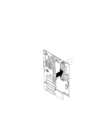
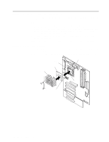
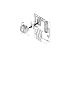
• If the drive is an IDE device, plug one connector of the IDE signal cable into the back of the drive and the other end of the cable into the IDE connector (IDE1) on the system board. For the location of the IDE connectors, see "System board internal cable connectors" on page 24. • If the drive is a SCSI device, your server must have a SCSI adapter installed. Plug one connector of the SCSI signal cable into the back of the drive and the other end of the cable into the connector on the SCSI adapter. See "Installing an adapter" on page 36. Note: Make sure to route the signal cable so that it does not block the air flow to the rear of the drives or over the microprocessor. 9. If you have another drive to install or remove, do so now. 10. Plug one of the power cables from the power supply into the back of the drive. The connectors are keyed and can be inserted only one way. 11. Replace the support-bracket assembly and reconnect the fan cable to the connector (SYSFA3) on the system board. See, "Removing the support-bracket assembly" on page 34 for details. See "System board internal cable connectors" on page 24 for the location of the fan cable connector. 12. If you have other options to install, do so now. 13. Reinstall the side cover. See "Installing the cover" on page 50 for details. 14. Reconnect the external cables and power cords; then, turn on the peripheral devices and the server. Installing a hard disk drive in bay 5, 6, or 7 Complete the following steps to install a hard disk drive in bay 5, 6, or 7. Drive cage retention tab Drive cage release tab 42 IBM xSeries 200: User's Reference
-
 1
1 -
2
-
3
-
4
-
5
-
6
-
7
-
8
-
9
-
10
-
11
-
12
-
13
-
14
-
15
-
16
-
17
-
18
-
19
-
20
-
21
-
22
-
23
-
24
-
25
-
26
-
27
-
28
-
29
-
30
-
31
-
32
-
33
-
34
-
35
-
36
-
37
-
38
-
39
-
40
-
41
-
42
-
43
-
44
-
45
-
46
-
47
-
48
-
49
-
50
-
 51
51 -
 52
52 -
 53
53 -
 54
54 -
 55
55 -
 56
56 -
 57
57 -
 58
58 -
 59
59 -
 60
60 -
 61
61 -
62
-
63
-
64
-
65
-
66
-
67
-
68
-
69
-
70
-
71
-
72
-
73
-
74
-
75
-
76
-
77
-
78
-
79
-
80
-
81
-
82
-
83
-
84
-
85
-
86
-
87
-
88
-
89
-
90
-
91
-
92
-
93
-
94
-
95
-
96
-
97
-
98
-
99
-
100
-
101
-
102
-
103
-
104
-
105
-
106
-
107
-
108
-
109
-
110
-
111
-
112
-
113
-
114
-
115
-
116
-
117
-
118
-
119
-
120
-
121
-
122
-
123
-
124
-
125
-
126
-
127
-
128
 |
 |
