IBM 8479 User Reference - Page 64
Installing the cover, Stock No. 176-735
 |
UPC - 087944653912
View all IBM 8479 manuals
Add to My Manuals
Save this manual to your list of manuals |
Page 64 highlights
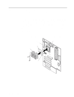
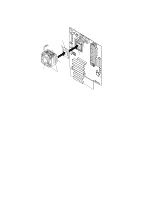
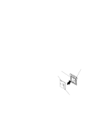
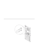
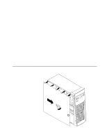
- A 19 mm (0.75 in.) U-bolt or wire rope (similar to National Manufacturing No. 3230, Stock No. 176-735) - Threaded nuts that fit the U-bolt - A security cable - A lock, such as a combination lock or padlock • Read "Safety information" on page 28 and "Handling static-sensitive devices" on page 27. Complete the following steps to install a U-bolt. 1. Turn off the server and peripheral devices and disconnect all external cables and power cords; then, remove the cover (see "Removing the side cover" on page 33 for details). 2. Use a screwdriver to remove the two metal knockouts. 3. Insert the U-bolt through the rear panel; then, attach and tighten the nuts. 4. If you have other options to install or remove, do so now. 5. Reinstall the side cover. See "Installing the cover" for details. 6. Thread the cable through the U-bolt and around an object that is a part of or permanently secured to the building structure or foundation, and from which it cannot be removed; then, fasten the cable ends together with a lock. 7. Reconnect the external cables and power cords; then, turn on the peripheral devices and the server. Installing the cover The following information describes the cover installation procedure. 50 IBM xSeries 200: User's Reference
-
 1
1 -
2
-
3
-
4
-
5
-
6
-
7
-
8
-
9
-
10
-
11
-
12
-
13
-
14
-
15
-
16
-
17
-
18
-
19
-
20
-
21
-
22
-
23
-
24
-
25
-
26
-
27
-
28
-
29
-
30
-
31
-
32
-
33
-
34
-
35
-
36
-
37
-
38
-
39
-
40
-
41
-
42
-
43
-
44
-
45
-
46
-
47
-
48
-
49
-
50
-
51
-
52
-
53
-
54
-
55
-
56
-
57
-
58
-
 59
59 -
 60
60 -
 61
61 -
 62
62 -
 63
63 -
 64
64 -
 65
65 -
 66
66 -
 67
67 -
 68
68 -
 69
69 -
70
-
71
-
72
-
73
-
74
-
75
-
76
-
77
-
78
-
79
-
80
-
81
-
82
-
83
-
84
-
85
-
86
-
87
-
88
-
89
-
90
-
91
-
92
-
93
-
94
-
95
-
96
-
97
-
98
-
99
-
100
-
101
-
102
-
103
-
104
-
105
-
106
-
107
-
108
-
109
-
110
-
111
-
112
-
113
-
114
-
115
-
116
-
117
-
118
-
119
-
120
-
121
-
122
-
123
-
124
-
125
-
126
-
127
-
128
 |
 |
