IBM 8479 User Reference - Page 61
If you are removing a fan sink from the microprocessor, disconnect the fan-sink
 |
UPC - 087944653912
View all IBM 8479 manuals
Add to My Manuals
Save this manual to your list of manuals |
Page 61 highlights
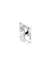
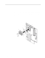
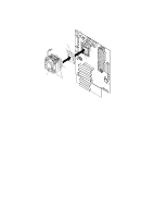
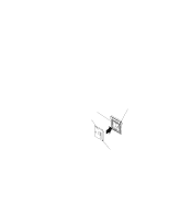
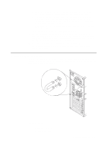
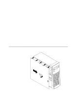
Note: This illustration shows the fan sink installed on the microprocessor. Microprocessor orientation indicator Microprocessor Microprocessor fan-sink connector (CPUFA1) Microprocessor connector Lever Tab Fan sink Thermal tape liner Retainer Complete the following steps to remove a microprocessor. Attention: When you handle static-sensitive devices, take precautions to avoid damage from static electricity. For details on handling these devices, see "Handling static-sensitive devices" on page 27. 1. Review the safety precautions listed in Statement 1 and Statement 5 in "Safety information" on page 28. 2. Turn off the server and peripheral devices and disconnect all external cables and power cords; then, remove the cover (see "Removing the side cover" on page 33 for details). 3. Remove the support-bracket assembly and disconnect the fan cable from the connector (SYSFA3) on the system board. See "Removing the support-bracket assembly" on page 34 for details. See "System board internal cable connectors" on page 24 for the location of the fan cable connector. 4. Push down and back on the retainer to remove it from the heat sink or the fan sink. Note: Allow sufficient time for a heat sink to cool, before you remove it from the microprocessor. 5. If you are removing a fan sink from the microprocessor, disconnect the fan-sink power cable from the microprocessor fan-sink connector located on the system board. See "System board internal cable connectors" on page 24 for the location. 6. Firmly grasp the heat sink or fan sink and lift it off the microprocessor. 7. Pull out and lift up the release lever and remove the microprocessor from the connector. Store the microprocessor in a static-protective package for possible future use. 8. To install a new microprocessor, continue with step 4 in "Installing a microprocessor" on page 48. Chapter 5. Installing options 47
-
 1
1 -
2
-
3
-
4
-
5
-
6
-
7
-
8
-
9
-
10
-
11
-
12
-
13
-
14
-
15
-
16
-
17
-
18
-
19
-
20
-
21
-
22
-
23
-
24
-
25
-
26
-
27
-
28
-
29
-
30
-
31
-
32
-
33
-
34
-
35
-
36
-
37
-
38
-
39
-
40
-
41
-
42
-
43
-
44
-
45
-
46
-
47
-
48
-
49
-
50
-
51
-
52
-
53
-
54
-
55
-
 56
56 -
 57
57 -
 58
58 -
 59
59 -
 60
60 -
 61
61 -
 62
62 -
 63
63 -
 64
64 -
 65
65 -
 66
66 -
67
-
68
-
69
-
70
-
71
-
72
-
73
-
74
-
75
-
76
-
77
-
78
-
79
-
80
-
81
-
82
-
83
-
84
-
85
-
86
-
87
-
88
-
89
-
90
-
91
-
92
-
93
-
94
-
95
-
96
-
97
-
98
-
99
-
100
-
101
-
102
-
103
-
104
-
105
-
106
-
107
-
108
-
109
-
110
-
111
-
112
-
113
-
114
-
115
-
116
-
117
-
118
-
119
-
120
-
121
-
122
-
123
-
124
-
125
-
126
-
127
-
128
 |
 |
