IBM 8479 User Reference - Page 57
Installing memory modules
 |
UPC - 087944653912
View all IBM 8479 manuals
Add to My Manuals
Save this manual to your list of manuals |
Page 57 highlights
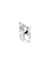
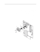
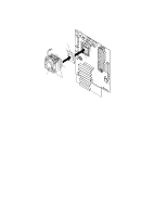
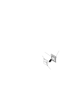
Attention: When you handle static-sensitive devices, take precautions to avoid damage from static electricity. For details on handling these devices, see "Handling static-sensitive devices" on page 27. 1. Read the information in "Preinstallation steps (all bays)" on page 40 and "Safety information" on page 28. 2. Turn off the server and peripheral devices and disconnect all external cables and power cords; then, remove the cover (see "Removing the side cover" on page 33 for details). 3. Remove the support-bracket assembly and disconnect the fan cable from the connector (SYSFA3) on the system board. See "Removing the support-bracket assembly" on page 34 for details. See "System board internal cable connectors" on page 24 for the location of the fan cable connector. 4. Access the drive cage. a. If your server has hard disk drives installed in the drive cage, disconnect the power and signal cables from the rear of the drives. b. Rotate the drive cage out of the server until it locks into place over the drive cage retention tab. Note: Before you install a hard disk drive, ensure that the drive cage locks into place over the drive cage retention tab by pressing on the side of the drive cage. 5. Touch the static-protective package containing the drive to any unpainted metal surface on the server; then, remove the drive from the package and place it on a static-protective surface. 6. Set any jumpers or switches on the drive according to the documentation that comes with the drive. 7. Attach the blue plastic guide rails to the sides of the drive using the screws and guide rails provided in the drive cage. 8. Slide the drive into the drive cage until the plastic tabs on the guide rails lock into place in the drive cage. 9. Lift the drive cage up and press in on the drive cage release tab; then, rotate the drive cage back into the server. Note: Clear any cables that might impede the replacement of the drive cage. 10. Connect the power and signal cables to the rear of each drive. Note: Make sure to route the signal cable so that it does not block the air flow to the rear of the drives or over the microprocessor. 11. If you have other options to install or remove, do so now. 12. Replace the support-bracket assembly and reconnect the fan cable to the connector (SYSFA3) on the system board. See "Removing the support-bracket assembly" on page 34 for details. See "System board internal cable connectors" on page 24 for the location of the fan cable connector. 13. Reinstall the side cover. See "Installing the cover" on page 50 for details. 14. Reconnect the external cables and power cords; then, turn on the peripheral devices and the server. Installing memory modules Adding memory to your server is an easy way to make programs run faster. You can increase the amount of memory in your server by installing options called memory modules. Your server uses a noninterleaved memory configuration. Chapter 5. Installing options 43
-
 1
1 -
2
-
3
-
4
-
5
-
6
-
7
-
8
-
9
-
10
-
11
-
12
-
13
-
14
-
15
-
16
-
17
-
18
-
19
-
20
-
21
-
22
-
23
-
24
-
25
-
26
-
27
-
28
-
29
-
30
-
31
-
32
-
33
-
34
-
35
-
36
-
37
-
38
-
39
-
40
-
41
-
42
-
43
-
44
-
45
-
46
-
47
-
48
-
49
-
50
-
51
-
 52
52 -
 53
53 -
 54
54 -
 55
55 -
 56
56 -
 57
57 -
 58
58 -
 59
59 -
 60
60 -
 61
61 -
 62
62 -
63
-
64
-
65
-
66
-
67
-
68
-
69
-
70
-
71
-
72
-
73
-
74
-
75
-
76
-
77
-
78
-
79
-
80
-
81
-
82
-
83
-
84
-
85
-
86
-
87
-
88
-
89
-
90
-
91
-
92
-
93
-
94
-
95
-
96
-
97
-
98
-
99
-
100
-
101
-
102
-
103
-
104
-
105
-
106
-
107
-
108
-
109
-
110
-
111
-
112
-
113
-
114
-
115
-
116
-
117
-
118
-
119
-
120
-
121
-
122
-
123
-
124
-
125
-
126
-
127
-
128
 |
 |
