IBM 8479 User Reference - Page 65
Connecting external options, I/O connector locations, and the server.
 |
UPC - 087944653912
View all IBM 8479 manuals
Add to My Manuals
Save this manual to your list of manuals |
Page 65 highlights
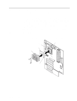
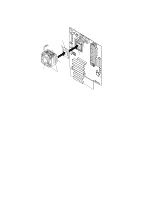
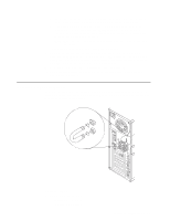
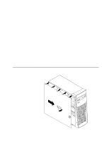
Notes: 1. The illustrations in this document might differ slightly from your hardware. 2. If you removed the support-bracket assembly after you removed the cover, reinstall it before you install the cover. See "Removing the support-bracket assembly" on page 34 for details. Complete the following steps to install the server cover. 1. Clear any cables that might impede the reinstallation of the cover. 2. Install the side cover: Note: The cover-release latch must be in the unlocked (opened) position before reinstalling the cover on the server. a. Insert the tabs located inside the cover into the slots located on the server chassis. b. Close the cover-release latch to secure the cover in place. Note: Make sure each tab on the cover is in its corresponding slot before closing the cover-release latch. 3. Lock the cover. 4. If you have not done so already, make sure the stabilizing feet are in the stabilizing position so that they properly support the server. See "Moving the stabilizing feet" on page 32 for details. 5. Connect the external cables and power cords; then, turn on the peripheral devices and the server. Connecting external options If you install a SCSI adapter in your server, you can attach a SCSI storage expansion enclosure. To attach an external device: 1. Read "Before you begin" on page 26 and the documentation that comes with your options. 2. Be sure your server and all peripheral devices are turned off. 3. Follow the instructions that come with the option to prepare it for installation and to connect it to the server. Note: If you are attaching a SCSI device, see "Ultra160 SCSI connector (some models)" on page 62 for SCSI ID and cabling information. I/O connector locations The following illustration shows the input/output connectors and the expansion slots on the rear of the server. For pin assignments and other details about these connectors, see "Input/output connectors" on page 52. Chapter 5. Installing options 51
-
 1
1 -
2
-
3
-
4
-
5
-
6
-
7
-
8
-
9
-
10
-
11
-
12
-
13
-
14
-
15
-
16
-
17
-
18
-
19
-
20
-
21
-
22
-
23
-
24
-
25
-
26
-
27
-
28
-
29
-
30
-
31
-
32
-
33
-
34
-
35
-
36
-
37
-
38
-
39
-
40
-
41
-
42
-
43
-
44
-
45
-
46
-
47
-
48
-
49
-
50
-
51
-
52
-
53
-
54
-
55
-
56
-
57
-
58
-
59
-
 60
60 -
 61
61 -
 62
62 -
 63
63 -
 64
64 -
 65
65 -
 66
66 -
 67
67 -
 68
68 -
 69
69 -
 70
70 -
71
-
72
-
73
-
74
-
75
-
76
-
77
-
78
-
79
-
80
-
81
-
82
-
83
-
84
-
85
-
86
-
87
-
88
-
89
-
90
-
91
-
92
-
93
-
94
-
95
-
96
-
97
-
98
-
99
-
100
-
101
-
102
-
103
-
104
-
105
-
106
-
107
-
108
-
109
-
110
-
111
-
112
-
113
-
114
-
115
-
116
-
117
-
118
-
119
-
120
-
121
-
122
-
123
-
124
-
125
-
126
-
127
-
128
 |
 |
