IBM 8479 User Reference - Page 59
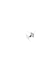
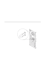
Install the DIMM, at each end of the DIMM connector. Firmly press the DIMM straight down into
 |
UPC - 087944653912
View all IBM 8479 manuals
Add to My Manuals
Save this manual to your list of manuals |
Page 59 highlights
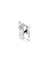
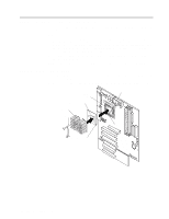
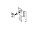
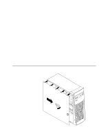
assembly" on page 34 for details. See "System board internal cable connectors" on page 24 for the location of the fan cable connector. 4. Install the DIMM: a. If you are installing a DIMM in connector 1, remove the AGP video adapter. Remove the AGP video adapter only if you are replacing the DIMM in connector 1. See "System and PCI extender-board option connectors" on page 24 for the location of the AGP slot. b. Open the retaining clip on each end of the DIMM connector. Attention: To avoid breaking the retaining clips or damaging the DIMM connectors, open and close the clips gently. c. Touch the static-protective package containing the DIMM to any unpainted metal surface on the server. Then, remove the DIMM from the package. d. Turn the DIMM so that the pins align correctly with the connector. e. Insert the DIMM into the connector by aligning the DIMM edges with the slots at each end of the DIMM connector. Firmly press the DIMM straight down into the connector by applying pressure on both ends of the DIMM simultaneously. Be sure that the retaining clips snap into the locked position when the DIMM is firmly seated in the connector. f. If a gap exists between the DIMM and the retaining clips, the DIMM has not been properly installed. In this case, open the retaining clips and remove the DIMM; then, reinsert the DIMM. g. If you removed the AGP video adapter, reinstall it now. See "Installing an adapter" on page 36. 5. If you have other options to install or remove, do so now. 6. Replace the support-bracket assembly and reconnect the fan cable to the connector (SYSFA3) on the system board. See "Removing the support-bracket assembly" on page 34 for details. See "System board internal cable connectors" on page 24 for the location of the fan cable connector. 7. Replace the side cover. See "Installing the cover" on page 50. 8. Reconnect the external cables and power cords; then, turn on the peripheral devices and the server. If you want to remove a DIMM, reverse these steps. Chapter 5. Installing options 45
-
 1
1 -
2
-
3
-
4
-
5
-
6
-
7
-
8
-
9
-
10
-
11
-
12
-
13
-
14
-
15
-
16
-
17
-
18
-
19
-
20
-
21
-
22
-
23
-
24
-
25
-
26
-
27
-
28
-
29
-
30
-
31
-
32
-
33
-
34
-
35
-
36
-
37
-
38
-
39
-
40
-
41
-
42
-
43
-
44
-
45
-
46
-
47
-
48
-
49
-
50
-
51
-
52
-
53
-
 54
54 -
 55
55 -
 56
56 -
 57
57 -
 58
58 -
 59
59 -
 60
60 -
 61
61 -
 62
62 -
 63
63 -
 64
64 -
65
-
66
-
67
-
68
-
69
-
70
-
71
-
72
-
73
-
74
-
75
-
76
-
77
-
78
-
79
-
80
-
81
-
82
-
83
-
84
-
85
-
86
-
87
-
88
-
89
-
90
-
91
-
92
-
93
-
94
-
95
-
96
-
97
-
98
-
99
-
100
-
101
-
102
-
103
-
104
-
105
-
106
-
107
-
108
-
109
-
110
-
111
-
112
-
113
-
114
-
115
-
116
-
117
-
118
-
119
-
120
-
121
-
122
-
123
-
124
-
125
-
126
-
127
-
128
 |
 |
