JVC GY-DV5000U GY-DV5000U 3-CCD Professional DV Camcorder 92 page instruction
JVC GY-DV5000U - 3-ccd Professional Dv Camcorder Manual
 |
View all JVC GY-DV5000U manuals
Add to My Manuals
Save this manual to your list of manuals |
JVC GY-DV5000U manual content summary:
- JVC GY-DV5000U | GY-DV5000U 3-CCD Professional DV Camcorder 92 page instruction - Page 1
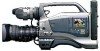
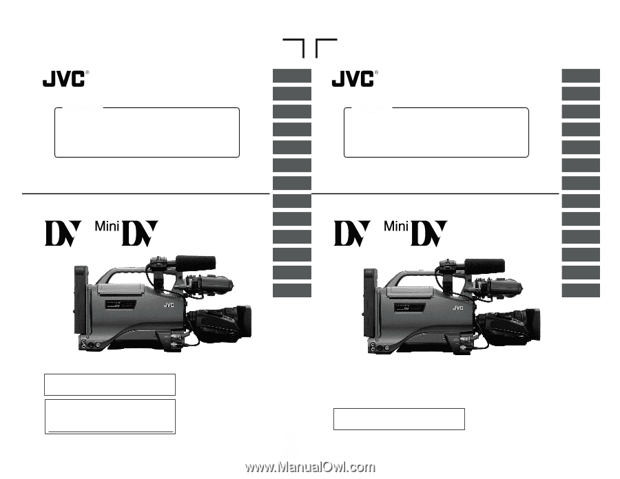
INSTRUCTIONS PLAYBACK MODE USING EXTERNAL COMPONENTS TIME CODE OPERATION MENU SCREENS FEATURES OF THE CAMERA SECTION OTHERS * The illustration shows the GY-DV5000 DV Camcorder with the optional lens, viewfinder, Microphone holder and Microphone attached. Thank you for purchasing this JVC - JVC GY-DV5000U | GY-DV5000U 3-CCD Professional DV Camcorder 92 page instruction - Page 2
of any service or repairs to this appliance, ask the service technician to perform routine safety checks to determine that the appliance is in safe operating condition. E Thank you for purchasing the JVC GY-DV5000 DV Camcorder. These instructions are for the GY-DV5000E. The instructions are given - JVC GY-DV5000U | GY-DV5000U 3-CCD Professional DV Camcorder 92 page instruction - Page 3
servicing) instructions MODIFICATIONS NOT APPROVED BY JVC COULD VOID USER'S use any other power source. NOTE: The rating plate (serial number plate) is on the top frame. CAUTION To prevent electric shock, do not open the cabinet. No user serviceable parts inside. Refer servicing to qualified service - JVC GY-DV5000U | GY-DV5000U 3-CCD Professional DV Camcorder 92 page instruction - Page 4
purchasing the DV Camcorder GY-DV5000. These instructions are for GY-DV5000. This unit is a DV video system format camcorder. Videocassettes marked with the symbol or symbol can be used. The following phenomena may occur when tapes recorded on other units (including another GY-DV5000) are recorded - JVC GY-DV5000U | GY-DV5000U 3-CCD Professional DV Camcorder 92 page instruction - Page 5
the replacement, adjustment and servicing of parts require advanced skill and equipment, please consult the person in charge of professional video equipment at your nearest JVC-authorized service agent. Head Cleaning ● To maintain beautiful pictures and sound, be sure to use a head cleaning tape to - JVC GY-DV5000U | GY-DV5000U 3-CCD Professional DV Camcorder 92 page instruction - Page 6
every 5 hours 1-4 Videocassette to be Used ● Use JVC's videocassette tapes marked with the " " or " " symbol. Standard DV videocassette: LA-DV276, LA-DV186, LADV124 Mini DV videocassette: M-DV63PRO, M-DV60, M-DV30 * Do not use M-DV80. ● Videocassettes cannot be used upside down. ● Avoid storing - JVC GY-DV5000U | GY-DV5000U 3-CCD Professional DV Camcorder 92 page instruction - Page 7
on the viewfinder or LCD areas having luminance levels in accordance with the menu settings made for the video signal. This pattern can be used as a reference for manual adjustment of the lens iris. Zebra patterns are also displayed during color bar display when this switch is set to ON. ☞ See - JVC GY-DV5000U | GY-DV5000U 3-CCD Professional DV Camcorder 92 page instruction - Page 8
the iris mode switch of the lens is in manual. ● The gain will vary Camera/Auto knee switch This switch is used to select the output signal. When the video signal from the shooting camera Camera mode to record the camera image. ● Select the VTR mode to playback or to input the DV signal from the DV - JVC GY-DV5000U | GY-DV5000U 3-CCD Professional DV Camcorder 92 page instruction - Page 9
be rotated so that it can be accommodated in the main body of the camera. ☞ See page 40. 3 LCD door lock and release knob To open use this control, set the CH1 AUDIO SELECT switch 8 to "MANUAL". This control works regardless of the setting of CH1 FRONT VR item on the AUDIO/VIDEO menu screen. To use - JVC GY-DV5000U | GY-DV5000U 3-CCD Professional DV Camcorder 92 page instruction - Page 10
VIDEO menu screen.) Camera mode: The camera image is output. VTR mode: The playback image is output in the VTR playback mode. When a DV signal (IEEE1394) is input, the EE image of the input video CAUTION: To prevent foreign objects from entering the internal parts of the VTR unit, do not leave the - JVC GY-DV5000U | GY-DV5000U 3-CCD Professional DV Camcorder 92 page instruction - Page 11
ON again to put the camera in the operating status. If the unit still does not work normally, please consult the person in charge of professional video equipment at your nearest JVC-authorized service agent. Using a DV cable (optional), a digital video component with DV connector can be connected - JVC GY-DV5000U | GY-DV5000U 3-CCD Professional DV Camcorder 92 page instruction - Page 12
are also used for the -1 CH-2 AUTO MANUAL DISPLAY PULL OPEN Camera mode, one of four status screens is displayed. (STATUS 0, STATUS 1, STATUS 2, STATUS 3) ● One type of screen is displayed in the VTR mode (DV battery voltage in 0.1 V steps. * This indication blinks when the remaining battery - JVC GY-DV5000U | GY-DV5000U 3-CCD Professional DV Camcorder 92 page instruction - Page 13
tape time (min) or tape type (Example: 95 min ( )) (when using MiniDV cassette), (when using standard cassette), DVCAM (when using DVCAM cassette) * DVCAM indicates IC Memory compatible DVCAM cassette. In the case of other DVCAM cassette than IC Memory compatible cassette, or is indicated. Audio - JVC GY-DV5000U | GY-DV5000U 3-CCD Professional DV Camcorder 92 page instruction - Page 14
AUTO MANUAL DISPLAY video in the Camera mode, PAL battery PRO cassette is used. The tape is ejected. Displayed when attempt is made to playback a tape recorded in the LP mode. Displayed when no videocassette is inserted and the VTR trigger button is pressed. Displayed when there is no input to the DV - JVC GY-DV5000U | GY-DV5000U 3-CCD Professional DV Camcorder 92 page instruction - Page 15
item is set to NORMAL. ■ Menu Setting Screen --- MENU --- CAMERA OPERATION.. CAMERA PROCESS AUDIO/VIDEO.. LCD/VF.. TC/UB/CLOCK.. OTHERS.. FILE MANAGE.. MENU ALL RESET CANCEL EXIT TOP MENU screen (Camera mode) Screen used for making various settings. The Menu Setting Screen appears when - JVC GY-DV5000U | GY-DV5000U 3-CCD Professional DV Camcorder 92 page instruction - Page 16
GY-DV5000 STANDARD PACKAGE TRIPOD BASE KA-550U FOCUS MANUAL UNIT HZ-FM13 (FUJINON) HZ-FM15 (CANON) ZOOM SERVO UNIT HZ-ZS13B CARRYING CASE TRIPOD TP-P300 DOLLY TP-P205 ANTON BAUER ANTON BAUER BATTERY BATTERY HOLDER (PRO PAC, MAGNUM, (QRQ27) TRIMPAC, HYTRON) ANTON BAUER BATTERY CHARGER - JVC GY-DV5000U | GY-DV5000U 3-CCD Professional DV Camcorder 92 page instruction - Page 17
GY-DV5000's power switch to "OFF" before the zoom lens is attached or detached. 3-3 Attaching the Viewfinder By changing the position of the viewfinder mount base on the camera use Sliding securing ring 2. Cap 4. Fastening screws Cap HEXAGON WRENCH 5. 1. 4. Stopper screw 3. Mounting guide - JVC GY-DV5000U | GY-DV5000U 3-CCD Professional DV Camcorder 92 page instruction - Page 18
POWER switch of the GY-DV5000 to ON. Power is supplied to the VTR section and the camera. * For details, read the instruction manual of the AA-P250. MEMO: Do not remove or connect the DC cable while recording is being performed. 4-2 Battery Pack Operation (Optional) The GY-DV5000 can be operated - JVC GY-DV5000U | GY-DV5000U 3-CCD Professional DV Camcorder 92 page instruction - Page 19
battery case from the GY-DV5000 and replace it with the Anton-Bauer battery holder. Use the following battery holder. • Battery holder: Anton-Bauer QRQ27 Detaching the Battery Case From the GY-DV5000 and Attaching The AntonBauer Battery Attaching the Anton-Bauer Battery Holder Anton-Bauer Battery - JVC GY-DV5000U | GY-DV5000U 3-CCD Professional DV Camcorder 92 page instruction - Page 20
CH-2 AUDIO INPUT AUDIO SELECT CH-1 CH-2 AUTO MANUAL DISPLAY PULL OPEN MENU AUTO IRIS FULL AUTO BACK L GY-DV5000 in the record-standby or STOP mode. 2. Set the POWER switch to OFF. 3. Remove the battery pack or the power supply to the DC IN connector. (When the camera is not going to be used - JVC GY-DV5000U | GY-DV5000U 3-CCD Professional DV Camcorder 92 page instruction - Page 21
be loaded or unloaded while the GY-DV5000 is in POWER OFF mode. ● Use a standard DV videocassette or a MiniDV videocassette. ● Press at the center . ■ The status when the tape is loaded differs with the mode of the GY-DV5000 (Camera mode or VTR mode) and the condition of the switch on the back of - JVC GY-DV5000U | GY-DV5000U 3-CCD Professional DV Camcorder 92 page instruction - Page 22
is briefly pressed while the LCD monitor is used for display, the contents change as follows. be set. Powered by the built-in backup battery the set date and time data continue to AUTO MANUAL DISPLAY PULL OPEN TOP MENU screen --- MENU --- CAMERA OPERATION.. CAMERA PROCESS.. AUDIO/VIDEO.. - JVC GY-DV5000U | GY-DV5000U 3-CCD Professional DV Camcorder 92 page instruction - Page 23
To return to the normal screen, use either of the following methods. Press time in the various operation modes. In Camera mode : The date and time of During DV signal input : The date and time from the DV connector ON. ● DATE REC item : Select the video mode in which date and time data should - JVC GY-DV5000U | GY-DV5000U 3-CCD Professional DV Camcorder 92 page instruction - Page 24
code data again. However, it is possible to use the GY-DV5000 even if the bulit-in battery is discharged but the date and time and time code data cannot be recorded. ■ How to charge AC outlet AA-P250 AC power adapter DC cable PHONES DV REAR AUDIO IN DC OUT DC IN TALLY 1. Connect - JVC GY-DV5000U | GY-DV5000U 3-CCD Professional DV Camcorder 92 page instruction - Page 25
Yellow Cyan Green Magenta Red Blue Display the camera built-in color bar signal on the video monitor and adjust the colors, contrast and brightness. 1. Connect a color video monitor to the MONITOR OUT connector of the GY-DV5000. 2. Set the COLOR BARS/CAMERA/AUTO KNEE switch to BARS to output the - JVC GY-DV5000U | GY-DV5000U 3-CCD Professional DV Camcorder 92 page instruction - Page 26
the camera is ● Set the IRIS mode switch of the lens to A (Auto). 2. Set the FILTER MANUAL COUNTER TC UB TC GENE. REGEN FREE REC PRST PHONES DV REAR AUDIO IN DC OUT DC IN TALLY REAR AUDIO IN connector The GY-DV5000 channel input sound Make the selection using the CH-2 AUDIO INPUT switch - JVC GY-DV5000U | GY-DV5000U 3-CCD Professional DV Camcorder 92 page instruction - Page 27
use the audio input level control on the front section, make the following settings. ● Set the CH-1 AUDIO SELECT switch to MANUAL. ● Set the CH-1 FRONT VR. item on the AUDIO/VIDEO end is reached or when the battery is running down. The volume otherwise howling with the camera microphone may occur. - JVC GY-DV5000U | GY-DV5000U 3-CCD Professional DV Camcorder 92 page instruction - Page 28
The CAM indicator lights up. The GY-DV5000 is in the Camera mode when the CAM indicator is on. Use a standard DV videocassette or a MiniDV videocassette. (When a DVCAM cassette is used or by removing the battery pack. ● Trial-shooting lens' iris if the iris is changed abruptly or the iris is manually - JVC GY-DV5000U | GY-DV5000U 3-CCD Professional DV Camcorder 92 page instruction - Page 29
SELECT CH-1 CH-2 AUTO MANUAL DISPLAY PULL OPEN EDITSEARCH ATUS Y/C OUT connectors. ● The video image from the VTR section is the RET button on the camera lens section. • The tape is camera will automatically return to recording mode after playback. * This function does not work when the GY-DV5000 - JVC GY-DV5000U | GY-DV5000U 3-CCD Professional DV Camcorder 92 page instruction - Page 30
CH-2 AUTO MANUAL DISPLAY PULL OPEN BLANK SEARCH REW STOP FF PLAY STILL MODE VTR CAM Still button PLAY button STOP button POWER switch MODE switch MEMO: ● The GY-DV5000 can play back the following three types of videocassettes: • DV videocassette • MiniDV videocassette • DVCAM videocassette - JVC GY-DV5000U | GY-DV5000U 3-CCD Professional DV Camcorder 92 page instruction - Page 31
SEARCH button. ● Blank search starts. When a blank part (unrecorded part) on the tape is detected, the unit enters DV input.) When the GY-DV5000 is used for playback of a tape that was recorded on another unit with audio recorded on the CH-3 and CH4 channels, the AUDIO SELECT item on the AUDIO/VIDEO - JVC GY-DV5000U | GY-DV5000U 3-CCD Professional DV Camcorder 92 page instruction - Page 32
AUDIO SELECT CH-1 CH-2 AUTO MANUAL DISPLAY PULL OPEN DV cable Signal flow Backup unit Connections Use the GY-DV5000 as the master unit. Connect the master unit and the backup unit with a DV cable Settings ■ Master unit (GY-DV5000) ● Place in CAMERA mode. ● Set the DV REC TRIGGER item on the - JVC GY-DV5000U | GY-DV5000U 3-CCD Professional DV Camcorder 92 page instruction - Page 33
The GY-DV5000 records code generator's running method is set to the drop frame mode. Use this setting when placing emphasis on the recording time. NON DROP : MANUAL DISPLAY PULL OPEN SHUTTER dial STATUS button TOP MENU screen --- MENU --- CAMERA OPERATION.. CAMERA PROCESS.. AUDIO/VIDEO.. - JVC GY-DV5000U | GY-DV5000U 3-CCD Professional DV Camcorder 92 page instruction - Page 34
FILE CAM2) on the GY-DV5000. When saving menu setting contents that remain more or less fixed, these are stored in FILE CAM1 or FILE CAM2. A saved file (FILE CAM1 or CAM2) can be read out on the FILE MANAGE menu screen. --- MENU --- CAMERA OPERATION.. CAMERA PROCESS.. AUDIO/VIDEO.. LCD/VF.. TC - JVC GY-DV5000U | GY-DV5000U 3-CCD Professional DV Camcorder 92 page instruction - Page 35
MANUAL DISPLAY PULL OPEN SHUTTER dial STATUS button SHUTTER STA MENU Cursor MENU screen --- MENU --- CAMERA OPERATION.. CAMERA PROCESS.. AUDIO/VIDEO Set the mode of the GY-DV5000 with the MODE switch. (Camera mode or VTR mode) 3. FILE MANAGE menu screen is used to perform the following tasks - JVC GY-DV5000U | GY-DV5000U 3-CCD Professional DV Camcorder 92 page instruction - Page 36
GY-DV5000 is in the Camera mode or in the VTR mode. In the VTR mode, the CAMERA OPERATION and CAMERA PROCESS menu screens are not displayed. Item Function Variation Range Initial Setting CAMERA NONE :FAW function is not used. A :FAW is assigned to image size of the video signal. 4:3 4:3 - JVC GY-DV5000U | GY-DV5000U 3-CCD Professional DV Camcorder 92 page instruction - Page 37
Using the Skin Detail Function" on page 86. ON OFF OFF SCAN Increases the vertical resolution. ● VIDEO the flare phenomenon in which light entering the lens is diffused and results in reflection that colors the SKIN COLOR ADJUST screen. The CAMERA PROCESS menu screen returns when the SHUTTER - JVC GY-DV5000U | GY-DV5000U 3-CCD Professional DV Camcorder 92 page instruction - Page 38
VIDEO DV format offers recording tracks for up to 4 channel when using 12-bit, 32 kHz sampling. The GY-DV5000 records two of these track. The GY-DV5000 L and R) Selects whether the camera image or VTR playback image should whether or not the F-number of the lens iris/iris level mark is displayed in - JVC GY-DV5000U | GY-DV5000U 3-CCD Professional DV Camcorder 92 page instruction - Page 39
whether or not the remaining tape time (minutes) is shown in the OFF ON status display on the LCD monitor or in the viewfinder. ON (Camera mode: Status 1 screen, VTR mode: Status screen) OFF : Not displayed. ON : Displayed. Selects whether or not the time code or user's bits data should be - JVC GY-DV5000U | GY-DV5000U 3-CCD Professional DV Camcorder 92 page instruction - Page 40
video data or not, as well as the video camera GY-DV5000's DV signal should be ON recorded on another component for backup. OFF : VTR trigger command is not output. ON : VTR trigger command is output. * Set this item to OFF, when the Backup Recording function of BR-DV600A or BR-DV3000 is used - JVC GY-DV5000U | GY-DV5000U 3-CCD Professional DV Camcorder 92 page instruction - Page 41
used battery back type. 12V 12V 12V : Choose this setting when using 12 V battery (12VDC Flat shape 13.2V type). 14.4V 13.2V : Choose this setting when using 13.2 V battery SELECT CH-1 CH-2 AUTO MANUAL DISPLAY PULL OPEN The FAW white balance or when the camera is moved frequently in and - JVC GY-DV5000U | GY-DV5000U 3-CCD Professional DV Camcorder 92 page instruction - Page 42
THE CAMERA SECTION 12-2 IRIS (Brightness) Adjustment ADJUSTMENT OF LENS IRIS Iris ring RET M A W T The lens iris can be adjusted using any the video signal. The zebra pattern can be used as a reference for manual iris adjustment. ● The initial setting is 70 to 80%. However, using the ZEBRA - JVC GY-DV5000U | GY-DV5000U 3-CCD Professional DV Camcorder 92 page instruction - Page 43
THE CAMERA SECTION 12-4 Shooting the Screen Image on a Computer Monitor Video SELECT CH-1 CH-2 AUTO MANUAL DISPLAY PULL OPEN SHUTTER dial --- CAMERA OPERATION --- SHUTTER VARIABLE FAW seconds. ■ When the LOLUX function is in use, the image definition on the screen will degrade to - JVC GY-DV5000U | GY-DV5000U 3-CCD Professional DV Camcorder 92 page instruction - Page 44
automatically to the camera image. ● The auto iris adjustment mode is entered even if the iris mode switch of the lens is set to manual. ● The GAIN 12. FEATURES OF THE CAMERA SECTION 12-7 How to Use Skin Detail The contour emphasis in the skin color areas of the video signal can be controlled and - JVC GY-DV5000U | GY-DV5000U 3-CCD Professional DV Camcorder 92 page instruction - Page 45
AUTO MANUAL DISPLAY Use a standard DV videocassette or MiniDV use is used. The tape is forcibly ejected. videocassette for video use. LP TAPE INVALID! Attempt to play back a tape recorded in the LP mode. The GY-DV5000 battery power is low. Remedy Prepare a charged battery or replace the battery - JVC GY-DV5000U | GY-DV5000U 3-CCD Professional DV Camcorder 92 page instruction - Page 46
service manual Warning Error Code Error Details GY-DV5000 Operation Remedy 0201 Indicates dew person in charge of professional video equipment at your nearest JVC-authorized service agent. TAPE DEFECTIVE Blinks when remaining battery power or tape is low. (Only in Camera mode) Blinking Pattern - JVC GY-DV5000U | GY-DV5000U 3-CCD Professional DV Camcorder 92 page instruction - Page 47
menu item setting is incorrect, set it correctly using the OTHERS (2/2) menu screen's item BATTERY Battery alarm is displayed and the GY- TYPE. DV5000 enters the non-operating mode ● Is the battery old? even when a fully charged battery is used. Cassette cannot be ejected after the power is - JVC GY-DV5000U | GY-DV5000U 3-CCD Professional DV Camcorder 92 page instruction - Page 48
Storage temperatures: -20 °C to 60 °C ■ ACCESSORIES Microphone Tripod base Hexagon wrench Instruction Manual : × 1 (SCV2987-004)* : × 1 (SCV3021-001)* : × 1 (LW40409-001A)* : ×1 * Service parts number For details, consult your JVC dealer. Design and specifications are subject to change without - JVC GY-DV5000U | GY-DV5000U 3-CCD Professional DV Camcorder 92 page instruction - Page 49
OPTIONAL ACCESSORIES Viewfinder Power zoom lens AC power adapter Microphone Microphone holder Network Pack : VF-P115B, VF-P116 : S14 × 7.3B12U, S17 × 6.6BRM, S20 × 6.4B12U (FUJINON) YH16 × 7K12U, YH19 × 6.7K12U (CANON) : AA-P250 : MV-P615U, MV-P618U : KA-A50U : KA-DV5000U EXTERNAL DIMENSIONS (
-
 1
1 -
 2
2 -
 3
3 -
 4
4 -
 5
5 -
 6
6 -
 7
7 -
8
-
9
-
10
-
11
-
12
-
13
-
14
-
15
-
16
-
17
-
18
-
19
-
20
-
21
-
22
-
23
-
24
-
25
-
26
-
27
-
28
-
29
-
30
-
31
-
32
-
33
-
34
-
35
-
36
-
37
-
38
-
39
-
40
-
41
-
42
-
43
-
44
-
45
-
46
-
47
-
48
-
49
 |
 |
GY-DV5000
LWT0072-001A
DV CAMCORDER
INSTRUCTIONS
* The illustration shows the GY-DV5000 DV Camcorder with the optional lens, viewfinder, Microphone holder
and Microphone attached.
This instruction manual is made from 100% recycled paper.
For Customer Use :
Enter below the Serial No. which is located on the body.
Retain this information for future reference.
Model No. GY-DV5000
Serial No.
Thank you for purchasing this JVC product. Before operating
this unit, please read the instructions carefully to ensure the
best possible performance.
INTRODUCTION
CONTROLS,
INDICATORS AND
CONNECTORS
BASIC SYSTEM
CONNECTIONS AND
ADJUSTMENTS
POWER SUPPLY
PREPARATIONS
SETTING AND
ADJUSTMENTS
BEFORE SHOOTING
SHOOTING
OPERATION
PLAYBACK MODE
USING EXTERNAL
COMPONENTS
TIME CODE
OPERATION
MENU SCREENS
OTHE
RS
FEATURES OF THE
CAMERA SECTION
GY-DV5000
LWT0090
DV CAMCORDER
INSTRUCTIONS
* The illustration shows the GY-DV5000 DV Camcorder with the optional lens and viewfinder Microphone holder, Microphone attache
d.
This instruction manual is made from 100% recycled paper.
Thank you for purchasing this JVC product. Before operating
this unit, please read the instructions carefully to ensure the
best possible performance.
INTRODUCTION
CONTROLS,
INDICATORS AND
CONNECTORS
BASIC SYSTEM
CONNECTIONS AND
ADJUSTMENTS
POWER SUPPLY
PREPARATIONS
SETTING AND
ADJUSTMENTS
BEFORE SHOOTING
SHOOTING
OPERATION
PLAYBACK MODE
USING EXTERNAL
COMPONENTS
TIME CODE
OPERATION
MENU SCREENS
O
THERS
FEATURES OF THE
CAMERA SECTION
E
U
CAUTION
This section of instruction manual is specially edited
for service purpose with modified contents.
It is not recommended to use this section for the sub-
stitution of the original book included in the merchan-
dise.
CAUTION
This section of instruction manual is specially edited
for service purpose with modified contents.
It is not recommended to use this section for the sub-
stitution of the original book included in the merchan-
dise.