JVC GY-DV5000U GY-DV5000U 3-CCD Professional DV Camcorder 92 page instruction - Page 7
Controls, Indicators And Connectors, 2- 1 Front - lens
 |
View all JVC GY-DV5000U manuals
Add to My Manuals
Save this manual to your list of manuals |
Page 7 highlights
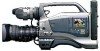
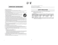
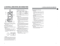
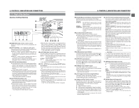
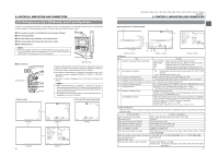
2. CONTROLS, INDICATORS AND CONNECTORS 2-1 Front Section q w !0 VF o e r t y OFF ZEBRA ON SKIN AREA AUTO WHITE ACCU FOCUS VTR AUDIO LEVELE CH-1 5 i u 1 Viewfinder mount base, sliding securing ring Mount the viewfinder on the base and secure it using the sliding securing ring. ☞ See "Attaching the Viewfinder" on page 30. 2 [VF] Viewfinder connector (6-pin) Connect the cable from the viewfinder here. 3 [FRONT AUDIO IN] Front audio input connector (XLR 3-pin) Balanced 3-pin connector for camera microphone or external audio component. ● Set the FRONT/REAR AUDIO INPUT switch ! on page 15 in accordance with the connected device. ● To record the audio from this connector, set the CH-1/ CH-2 AUDIO INPUT switch 0 on page 15 to "FRONT". ☞ See page 15. 1 3 2 Pin No. 1 2 3 Function GND HOT COLD 4 [LENS] Lens control connector Connect 12-pin lens control cable from lens here. Pin No. Function Pin No. Function 1 Return switch 7 2 VTR trigger 8 3 GND 9 4 Lens AUTO/MANU control 10 5 IRIS control 11 6 +12V DC 12 Iris position IRIS A/R INPUT EXTENDER position ZOOM position - - 5 [ZEBRA] Switch When this switch is ON, a zebra pattern is imposed on the viewfinder or LCD areas having luminance levels in accordance with the menu settings made for the video signal. This pattern can be used as a reference for manual adjustment of the lens iris. Zebra patterns are also displayed during color bar display when this switch is set to ON. ☞ See "Zebra Pattern Display during Manual Adjustment" on page 80. ● The default value is 70% - 80%. The luminance level can be changed with the ZEBRA setting in the LCD/VF menu screen. ☞ See "ZEBRA" item on page 73. While this switch is pressed to the SKIN AREA side, the color tone areas specified with the SKIN COLOR ADJUST item on the ADVANCED PROCESS menu are indicated in the viewfinder.The switch returns to the OFF position when released. ☞ See "How to Use Skin Detail" on page 85. ● The Skin Detail color tone areas are not indicated while the color bar or VTR playback picture is shown in the viewfinder or on the LCD monitor. 6 [VTR] VTR trigger button (record start/stop button) Recording start/stop can be done with this button. (It is interlocked with the VTR trigger button on the side section and the VTR trigger button on the lens section.) 7 [AUDIO LEVEL CH-1] CH-1 audio level control Adjusts the audio level of the CH1 audio signal input. Normally, the camera is used with the control set to the maximum (10) position. ● To use this control, set the CH1 FRONT VR item on the AUDIO/VIDEO menu screen to "ENABLE". CAUTION: The provided microphone is a phantom microphone. Please confirm that the FRONT AUDIO INPUT switch is set to the +48V side when the provided microphone should be used. When using a microphone other than a phantom microphone, first set the FRONT AUDIO INPUT switch to "LINE" or "MIC" before connecting the microphone. 10 2. CONTROLS, INDICATORS AND CONNECTORS 8 [AUTO WHITE/ACCU FOCUS] switch White Balance: ● First, position a white object to occupy 80% of the centre of the screen. ● When the WHT.BAL switch % on page 13 is set to A or B, setting this switch to the upper position ("AUTO WHITE") will provide automatic adjustment for white balance. * It is not activated in preset, full auto shooting, full-time auto white balance and color bar modes. ☞ See "White Balance Adjustment" on page 48. ACCU-FOCUS: ● When this switch is pressed down to "ACCU FOCUS", the lens iris will be forced to open for approximately ten seconds. ● The depth of field can be reduced and the lens focusing can be adjusted more accurately. CAUTION: • As the automatic shutter is activated up to 1/10000, flicker may appear on the screen depending on the lighting conditions (such as a fluorescent lamp, etc.) • This operation is not effected in the LOLUX mode. 9 Lens mounting ring/Lens lock lever Hold the lens and use the lever to turn the ring anticlockwise to release lens. To mount lens make sure the lens guide pin fits well, and then turn the ring clockwise until firm. ☞ See "Attaching the Zoom Lens" on page 30. 0 [FILTER] Color temperature conversion filter control knob This knob switches the internal color temperature filters. (3200K, 5600K + 1/8ND, 5600K, 5600K + 1/64ND) ☞ See "Camera Settings" on page 45. 11
-
 1
1 -
 2
2 -
 3
3 -
 4
4 -
 5
5 -
 6
6 -
 7
7 -
 8
8 -
 9
9 -
 10
10 -
 11
11 -
 12
12 -
13
-
14
-
15
-
16
-
17
-
18
-
19
-
20
-
21
-
22
-
23
-
24
-
25
-
26
-
27
-
28
-
29
-
30
-
31
-
32
-
33
-
34
-
35
-
36
-
37
-
38
-
39
-
40
-
41
-
42
-
43
-
44
-
45
-
46
-
47
-
48
-
49
 |
 |