JVC GY-DV5000U GY-DV5000U 3-CCD Professional DV Camcorder 92 page instruction - Page 45
OTHERS, 13- 1 Alarm Indications and Actions, OTHERS
 |
View all JVC GY-DV5000U manuals
Add to My Manuals
Save this manual to your list of manuals |
Page 45 highlights
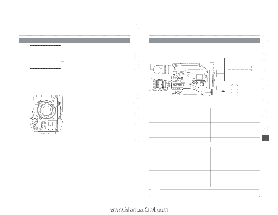
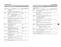
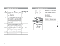
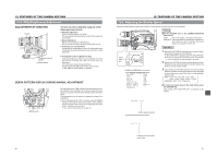
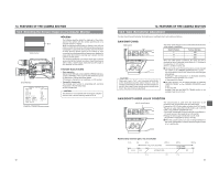
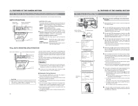
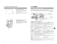
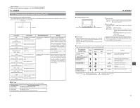
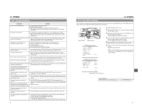
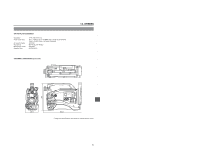
12. FEATURES OF THE CAMERA SECTION 12-7 How to Use Skin Detail (Cont'd) FAS 6dB FAW I SD B 12.2V 01/02/03 01:23:45 Status 0 "SD" display ■ Using the Skin Detail Function To use the skin detail function set on the SKIN COLOR ADJUST screen, select "ON" for the SKIN DTL DETECT item on the CAMERA PROCESS menu screen. While the Skin Detail function operates, the "SD" indicator is displayed on the Status 0 and Status 1 screen in the viewfinder or LCD monitor. OFF ZEBRA ON SKIN AREA AUTO WHITE ACCU FOCUS VTR AUDIO LEVELE CH-1 5 ZEBRA switch ■ Confirming the color tone area adjusted with the Skin Detail function When the ZEBRA switch on the front section is pressed to the "SKIN AREA" side, zebra patterns are indicated in the colour tone areas adjusted with Skin Detail and displayed in the viewfinder or on the LCD monitor. 86 13. OTHERS 13-1 Alarm Indications and Actions The GY-DV5000 displays messages on the LCD monitor and in the viewfinder in the case of improper operation, notices on remaining battery power and tape and warnings in the case of abnormalities during VCR operation. Also, when remaining tape or battery power becomes small, or in the case of abnormalities during VCR operation, the TALLY lamps and viewfinder lamp will blink (or light steadily), and alarm sound will be output through the monitoring loudspeaker or the PHONES jack. B: Alarm display area TALLY lamp EDITSEARCH FILTER 1 3200K 2 5600K 1/8 ND .3 5600K .4 5600K 1/64 ND SHUTTER STATUS MONITOR MENU AUTO IRIS FULL AUTO BACK L NORMAL SPOT L BLACK LOLUX STRETCH NORMAL COMPRESS MODE VTR CAM POWER VTR ON OFF OPEN CH-1 AUDIO LEVEL CH-2 LCD BRIGHT FRONT REAR CH-1 CH-2 AUDIO INPUT AUDIO SELECT CH-1 CH-2 AUTO MANUAL DISPLAY PULL OPEN TALLY lamp LOW VOLTAGE FAS dB NO TAPE FAW I B 12.2V 01/02/03 01:23:45 A: Improper operation caution area PHONES jack (Alarm sound) Monitoring loudspeaker (alarm sound) ■ Screen indications on the LCD monitor and in the Viewfinder ● Improper operation caution area (Display area: A) Indication Condition Remedy INVALID TAPE! A data tape for PC or DVCPRO videocassette Use a standard DV videocassette or MiniDV use is used. The tape is forcibly ejected. videocassette for video use. LP TAPE INVALID! Attempt to play back a tape recorded in the LP mode. The GY-DV5000 cannot play back tapes recorded in the LP mode. NO DV SIGNAL! DV signal is not input. Input a DV signal. COPY INHIBIT Attempt to record a copy-guarded DV signal. A copy-guarded DV signal cannot be input. REC INHIBIT An unrecordable videocassette (the switch on the Set the switch on the back of the cassette to "REC". back of the cassette is set to "SAVE") is loaded. NO TAPE No videocassette is loaded. Insert a videocassette. ● Alarm area (Display area: B) Indication LOW VOLTAGE Condition Remaining battery power is low. Remedy Prepare a charged battery or replace the battery immediately. TAPE NEAR END The remaining tape is 3 minutes or less. (Only To continue the recording, prepare a new tape or replace displayed in the shooting mode.) with a new tape immediately. HEAD CLEANING Displayed in case of video head clogging. (Head Clean the head with the special head cleaning tape. (See REQUIRED! clogging is detected and indicated during edit page 8.) search in the recording mode and during playback.) COPY GUARD! Attempt to play back a copy-guarded tape. A copy-guarded tape cannot be played back. CLOSE CASSETTE The cassette cover is open. COVER! Close the cassette cover. OPEN CASSETTE The cassette cover is closed. COVER! Open the cassette cover. MEMO: The GY-DV5000 is a microcomputer-controlled piece of equipment, which may malfunction due to external noise or interference. In this case, turn the power OFF, and then turn it ON again. 87
-
 1
1 -
2
-
3
-
4
-
5
-
6
-
7
-
8
-
9
-
10
-
11
-
12
-
13
-
14
-
15
-
16
-
17
-
18
-
19
-
20
-
21
-
22
-
23
-
24
-
25
-
26
-
27
-
28
-
29
-
30
-
31
-
32
-
33
-
34
-
35
-
36
-
37
-
38
-
39
-
 40
40 -
 41
41 -
 42
42 -
 43
43 -
 44
44 -
 45
45 -
 46
46 -
 47
47 -
 48
48 -
 49
49
 |
 |