JVC GY-DV5000U GY-DV5000U 3-CCD Professional DV Camcorder 92 page instruction - Page 13
Indications on the LCD Monitor and in the, Viewfinder Cont'd, Status Screen - dvcam
 |
View all JVC GY-DV5000U manuals
Add to My Manuals
Save this manual to your list of manuals |
Page 13 highlights
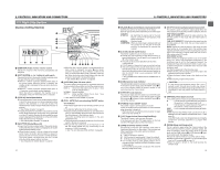
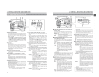
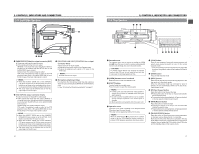
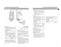
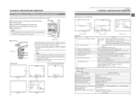
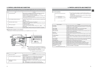
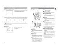
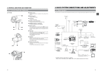
2. CONTROLS, INDICATORS AND CONNECTORS 2-6 Indications on the LCD Monitor and in the Viewfinder (Cont'd) ● Status 1 In addition to the information on the Status 0 screen, this screen displays the following items. No. Item 0 Time Code (TC)/User's Bits (UB) indication A Remaining tape indication B Audio sampling frequency indication C Audio level meter indication D VTR mode indication E Iris indicator display F Iris F-value indication G Filter position indication H Standard audio level indication 22 Contents Indicates the time code (h:m:s:frame) or user's bits data. (Example) Time code TC 00 : 00 : 00 : 00 Non-drop frame: Colon (:) User's bits UB FF EE DD 20 Drop frame: Dot (.) Whether or not to display this item is set with the TC/UB item on the LCD/ VF (2/2) menu screen. Whether the time code or user's bits should be shown is selected with the COUNTER switch inside the side cover. Remaining tape indication (displayed in 1-minute steps) This indicator blinks when remaining tape time is equivalent to less than 3 minutes. Whether or not to display this item is set with the TAPE REMAIN item on the LCD/VF (2/2) menu screen. * When inserting a brand-new tape, the remaining tape time is not indicated. When the tape has been run, the indication will appear. * The remaining tape indication is to be regarded only as a guide. * When the unit is used at low temperatures, it may take a while before the indication of the remaining tape time appears. 32 K : Indicated when the AUDIO MODE item on the AUDIO/VIDEO menu screen is set to 32 K. (Audio is recorded with 12-bit, 32 kHz sampling.) 48 K : Indicated when the AUDIO MODE item on the AUDIO/VIDEO menu screen is set to 48 K. (Audio is recorded with 16-bit, 48 kHz sampling.) Displays the CH-1, CH-2 audio level meters. Whether or not to display this item is set with the AUDIO DISPLAY item on the LCD/VF (2/2) menu. STBY : In record standby mode (record-pause mode) REC : During recording ED.FWD : Edit search in forward direction ED.REV : Edit search in reverse direction PLAY : During playback FF : During fast forward REW : During rewind STL : During still picture playback mode BSRH : During blank search FWD : During playback in forward direction (FWD1: About X5 speed, FWD2: About ×9 speed, FWD3: About X20 speed) REV : During playback in reverse direction (REV1: About X5 speed, REV2: About ×9 speed, REV3: About X20 speed) STOP : Stop mode (Tape protect mode) EJECT : Cassette being ejected - - - : No tape loaded ▲ : Iris set higher than normal ■ : Iris set to normal ▼ : Iris set lower than normal Indicates the F-number of the connected lens. OPEN, F2, F2.8, F4, F5.6, F8, F11, F16, CLOSE It is not displayed when the lens is removed. For some lenses, no display appears. The indication can be switched ON/OFF with the F.NO/IRIS IND. item on the LCD/VF (1/2) menu screen. Indicates the current filter position FIL1, FIL2, FIL3, FIL4 The indication can be switched ON/OFF with the FILTER item on the LCD/ VF (1/2) menu screen. The level at which audio is recorded on the tape is indicated by "■". -20dB, -12dB ☞ See "AUDIO REF. LEVEL" on page 72. -20dB -12dB ❘❘ CH 1 CH 1 CH 2 2. CONTROLS, INDICATORS AND CONNECTORS ● Status 2 This screen displays the camera setup statuses. Event display is not available while this screen is displayed. Indication FULL AUTO GAIN SHUTTER WHITE BAL IRIS LEVEL ZEBRA FILTER REMAIN AUDIO Indication Contents ON, OFF -3 dB, 0 dB, 3dB, 6 dB, 9 dB, 12 dB, 15dB, 18 dB, LOLUX, ALC OFF, 1/7.5, 1/15, 1/30, 1/60, 1/100, 1/250. 1/500, 1/1000, 1/2000, 1/4000, 1/10000 (STEP), V.SCAN 1/60.1 to 1/2084.6 (VARIABLE), EEI (in ALC mode) (U model) A, B, PRESET, FAW BACK L, NORMAL, SPOT L 70-80%, 85-95%, OVER95%, OVER100% 3200K, 5600K+1/8ND, 5600K, 5600K+1/64ND Remaining tape time (min) or tape type (Example: 95 min ( )) (when using MiniDV cassette), (when using standard cassette), DVCAM (when using DVCAM cassette) * DVCAM indicates IC Memory compatible DVCAM cassette. In the case of other DVCAM cassette than IC Memory compatible cassette, or is indicated. Audio sampling frequency and audio level adjustment method (Example) 32K (CH1 Å CH2 ˜ ) Å (Auto) ˜ (Manual) ● Status 3 This screen only displays date and time, event display and warning indications. * Whether or not date and time should be displayed and the display style are set on the TIME DATE MENU screen. ☞ page 43 "Displaying the Time and Date on the Screen" ■ Status Screen in VTR MODE (DV Signal Input Mode) 1 00:00:00:00 20min 3 9 Event display area 6 48k 12.2V 4 8 PLAY 01/02/03 AM01:23:45 7 5 No. Item Contents 1 Indication of Time Code (TC)/User's Bits (UB) In the playback mode, the recorded time code (hour, minute, second, frame) is displayed. Whether or not to display this item is set with the TC/UB item on the LCD/VF (2/2) menu screen. Whether to show the time code or the user's bits is selected with the COUNTER switch inside the side cover. 2 Remaining tape time Remaining tape indication (displayed in 1-minute steps) This indicator blinks when remaining tape time is equivalent to less than 3 minutes. Whether or not to display this item is set with the TAPE REMAIN item on the LCD/VF (2/2) menu screen. * When inserting a brand-new tape, the remaining tape time is not indicated. When the tape has been run, the indication will appear. * The remaining tape indication is to be used only as a guide. * When the unit is used at low temperatures, it may take a while before the indication of the remaining tape time appears. 3 Voltage indication (Example) 12.2 V : Indicates battery voltage in 0.1 V steps. * This indicator blinks when the remaining battery power is low. OFF, 1/6.25, 1/12.5, 1/25, 1/50, 1/120, 1/250, 1/500, 1/1000, 1/2000, 1/4000, 1/10000 (STEP), ← V.SCAN 1/50.1 to 1/2067.8 (VARIABLE), EEI (in ALC mode) (E model) 23
-
 1
1 -
2
-
3
-
4
-
5
-
6
-
7
-
 8
8 -
 9
9 -
 10
10 -
 11
11 -
 12
12 -
 13
13 -
 14
14 -
 15
15 -
 16
16 -
 17
17 -
 18
18 -
19
-
20
-
21
-
22
-
23
-
24
-
25
-
26
-
27
-
28
-
29
-
30
-
31
-
32
-
33
-
34
-
35
-
36
-
37
-
38
-
39
-
40
-
41
-
42
-
43
-
44
-
45
-
46
-
47
-
48
-
49
 |
 |
