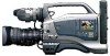
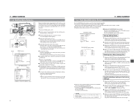
JVC GY-DV5000U GY-DV5000U 3-CCD Professional DV Camcorder 92 page instruction - Page 38
9 AUDIO/ VIDEO Menu Screen, 11- 10 LCD/ VF Menu Screen
 |
View all JVC GY-DV5000U manuals
Add to My Manuals
Save this manual to your list of manuals |
Page 38 highlights
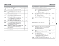
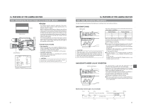
11. MENU SCREENS 11-9 AUDIO/VIDEO Menu Screen Item TEST TONE AUDIO MODE A.OUT AT SEARCH CH1 FRONT VR WIND CUT AUDIO REF. LEVEL AUDIO SELECT Function Variation Range Initial Setting Sets whether or not the audio reference signal (1kHz, -20dBFS or -12dBFS) should be output while the color bar is output. OFF: Audio reference signal is not output. ON: Audio reference signal is output. OFF ON OFF Selects the sampling frequency for audio recording (both CH-1 and CH- 32K 48K 2) 48K 32K : Recording is performed with 12-bit, 32 kHz sampling frequency 48K : Recording is performed with 16-bit, 48 kHz sampling frequency * The DV format offers recording tracks for up to 4 channel when using 12-bit, 32 kHz sampling. The GY-DV5000 records two of these track. The GY-DV5000 does not allow after-recording. Selects whether or not audio should be output during search. OFF : Audio is not output ON : Audio is output OFF ON ON Used to select whether or not the front section audio level control should be operative. The front section audio level control only affects the audio signal recorded on CH1. DISABLE: Use of the front section audio level control is disabled. ENABLE: Use of the front section audio level control is enabled. * The operation of the CH-1 audio level control on the side section is unaffected by this setting. DISABLE ENABLE ENABLE To select whether or not the low frequencies of the audio signal from the audio input connectors are cut. Set to ON to reduce the wind noise of the microphone. OFF : Low frequencies are not cut. FRONT : Only the low frequencies of the audio signal input to the FRONT AUDIO IN connector are cut. REAR : Only the low frequencies of the audio signal input to the REAR AUDIO IN connector are cut. BOTH : The low frequencies are cut for both the FRONT and REAR AUDIO IN connectors. OFF FRONT REAR BOTH OFF Sets the reference audio level of the tape (both CH-1 and CH-2). -20dB : Records with -20 dB as the reference audio level. -12dB : Records with -12 dB as the reference audio level. Use this setting when playing back the tape using DV equipment for general consumer use. * Use the same setting for playback as for recording. * This setting is unrelated to the audio level of the IEEE 1394 signal. -20dB -12dB -20dB Used to select which channels to reproduce when playing back a tape with sound recorded on 4 channels. (Can only be set in the VTR mode.) CH1/2 : To reproduce the sound recorded on CH-1 and CH-2. The GY-DV5000 records audio on the CH-1 and CH-2 channels during shooting. MIX : To simultaneously reproduce the sound of all four channels. CH3/4 : To reproduce the sound of the CH-3 and CH-4 channels. MEMO: The GY-DV5000 does not allow after-recording on the CH-3 and CH4 channels. CH1/2 MIX CH3/4 CH1/2 AUDIO MONITOR SET UP PAGE BACK Selects whether stereo sound or mixed sound is output from the PHONES jack when the MONITOR SELECT switch is set to MIX. STEREO : Stereo sound (CH-1 audio is output from L, CH-2 audio is output from R) * Only audio of CH-1 is output from the monitoring loudspeaker. MIX : Mixed sound (The mixed CH-1 and CH-2 audio is output from L and R) Selects whether the camera image or VTR playback image should be provided with the setup signal. * Setup signal can be selected even for IEEE1394 signal input. 0.0% : Setup signal is not attached to the recording/playback signal. 7.5% : Setup signal is attached to the recording/playback signal. The TOP MENU screen returns when the SHUTTER dial is pressed while the cursor is at this position. STEREO MIX 0.0% 7.5% ----- MIX 7.5% ----- 72 11. MENU SCREENS 11-10 LCD/VF Menu Screen The LCD/VF menu screen consists of two screens. (1/2 screen, 2/2 screen) ■ LCD/VF (1/2) Menu Screen Settings can be made on the LCD/VF (1/2) menu screen only in the Camera mode. Item Function Variation Range Initial Setting ZEBRA Switches the luminance level of the subject sections where the zebra pattern is displayed. 70-80% : Zebra pattern is displayed in sections with luminance levels between 70% and 80%. 85-95% : Zebra pattern is displayed in sections with luminance levels between 85% and 90%. OVER 95% : Zebra pattern is displayed in sections with luminance levels over 95%. OVER 100% : Zebra pattern is displayed in sections with luminance levels over 100%. 70-80% 85-95% OVER 95% OVER 100% 70-80% F.NO/ IRIS IND. Selects whether or not the F-number of the lens iris/iris level mark is displayed in the status display on the LCD monitor or in the viewfinder. (Status 1 screen) OFF : F-number and iris level mark is not displayed. F.NO : F-number is displayed. F.NO+IND. : F-number and iris level mark is displayed. OFF F.NO F.NO+IND. OFF FILTER Selects whether or not the FILTER position of the unit is displayed in the status display on the LCD monitor or in the viewfinder. (Status 1 screen) OFF : FILTER position is not displayed. ON : FILTER position is displayed. OFF ON OFF SAFETY ZONE Selects whether or not the safety zone is shown on the LCD monitor or in the viewfinder together with the form of the safety zone indication. OFF : Not displayed NORMAL : 4:3 zone is displayed. 16:9 : 16:9 zone is displayed. OFF NORMAL 16:9 OFF CENTER Sets whether or not a center mark is displayed when the safty zone is ON ON MARK displayed. OFF ON : Center mark is displayed. OFF : Center mark is not displayed. CAUTION: When the SAFETY ZONE item is set to OFF, "- - -" is indicated and this item cannot be selected. NEXT PAGE PAGE BACK To display the LCD/VF (2/2) menu screen, align the cursor with this item and then press the SHUTTER dial. The TOP MENU screen returns when the SHUTTER dial is pressed while the cursor is at this position. ----- ----- ----- ----- 73
-
 1
1 -
2
-
3
-
4
-
5
-
6
-
7
-
8
-
9
-
10
-
11
-
12
-
13
-
14
-
15
-
16
-
17
-
18
-
19
-
20
-
21
-
22
-
23
-
24
-
25
-
26
-
27
-
28
-
29
-
30
-
31
-
32
-
 33
33 -
 34
34 -
 35
35 -
 36
36 -
 37
37 -
 38
38 -
 39
39 -
 40
40 -
 41
41 -
 42
42 -
 43
43 -
44
-
45
-
46
-
47
-
48
-
49
 |
 |