JVC GY-DV5000U GY-DV5000U 3-CCD Professional DV Camcorder 92 page instruction - Page 12
6 Indications on the LCD Monitor and in the Viewfinder, CONTROLS, INDICA, TORS AND CONNECTORS - battery
 |
View all JVC GY-DV5000U manuals
Add to My Manuals
Save this manual to your list of manuals |
Page 12 highlights
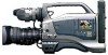
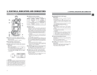
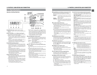
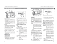
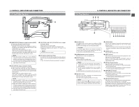
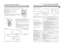
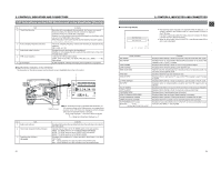
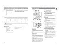
2. CONTROLS, INDICATORS AND CONNECTORS 2-6 Indications on the LCD Monitor and in the Viewfinder In addition to showing the EE image and the playback picture, the LCD monitor and viewfinder are also used for the following character displays. To show characters on the LCD monitor, press the DISPLAY button briefly. ■ Status screens (screens for checking the current camera settings) ■ Alarm message display ■ Auto white display (only displayed in the Camera mode) ■ Safety zone display (only displayed in the Camera mode) ■ Menu setting screens MEMO: ● When the OUTPUT CHAR. item on the OTHERS (1/2) menu screen is set to ON, the character displays mentioned above are also output through the MONITOR OUT connector and Y/C OUT connector. OPEN CH-1 AUDIO LEVEL CH-2 LCD BRIGHT FRONT REAR CH-1 CH-2 AUDIO INPUT AUDIO SELECT CH-1 CH-2 AUTO MANUAL DISPLAY PULL OPEN ■ Status Screens STATUS button EDITSEARCH FILTER 1 3200K 2 5600K 1/8 ND .3 5600K .4 5600K 1/64 ND SHUTTER STATUS MONITOR MENU AUTO IRIS FULL AUTO BACK L NORMAL SPOT L BLACK LOLUX STRETCH NORMAL COMPRESS MODE VTR CAM POWER VTR ON OFF ● Camera mode FAS 6dB FAW I SD B 12.2V 01/02/03 01:23:45 STATUS 0 01/02/03 01:23:45 STATUS 3 20 FIL1 F5.6 STBY DISPLAY button Press the STATUS button while normal screen is displayed to show one of the status screens. The contents of the status display are divided into those for the Camera mode and those for the VTR mode. ● Each time the STATUS button is pressed in the Camera mode, one of four status screens is displayed. (STATUS 0, STATUS 1, STATUS 2, STATUS 3) ● One type of screen is displayed in the VTR mode (DV signal input mode). MEMO: ● When the STATUS button is pressed for 1 second or longer, the menu setting screen is displayed. To display the Status screen while the menu setting screen is displayed, press the STATUS button to return to the normal screen. ● The DISPLAY button can be pressed to show characters alone in magnified size on the LCD monitor. ● VTR mode (DV signal input mode) 00:00:00:00 20min SKIN AREA FAS 6dB FAW I SD B 48k 12.2V 01/02/03 01:23:45 STATUS 1 00:00:00:00 20min PLAY 48k 12.2V 01/02/03 01:23:45 STATUS FULL AUTO GAIN SHUTTER WHITE BAL IRIS LEV. FILTER ZEBRA REMAIN AUDIO ON 6dB(L:0 M:9 H:18) 1/1000 A NORMAL 3200K 70%-80% 123 min( ) 32K( CH1 M CH2 M ) STBY 01/02/03 01:23:45 STATUS 2 SHUTTER 1/6.25, 1/12.5, 1/25, 1/50, 1/120, 1/250, 1/500, 1/1000, 1/2000, 1/4000, 1/10000 ← (E model) 2. CONTROLS, INDICATORS AND CONNECTORS ■ Status Screens in the Camera Mode 9 0 Event display area SKIN AREA FAS -3dB FAW 1 2 3 I 4 SD 5 H B 6G 12.2V 7 01/02/03 AM01:23:45 FIL1 F5.6 STBY 00:00:00:00 20min A FAS -3dB Event display area FAW I SD B 48k 12.2V 01/02/03 AM01:23:45 FULL AUTO GAIN SHUTTER WHITE BAL IRIS LVL. FILTER ZEBRA REMAIN AUDIO ON 6dB(L:0 M:9 H:18) 1/1000 A NORMAL 3200K 70-80% 123min( ) 32k(CH1 M CH2 M) 8 F D EC B STATUS 0 Screen STATUS 1 Screen STATUS 2 Screen ● Status 0 No. Item Contents 1 Indication of various function operations 2 Gain operation indication 3 Indication of FAW operation ACCU-FOCUS : Blinks during the ACCU-FOCUS operation. SKIN AREA : Blinks while the skin tone detail color area is displayed. ALC : Displayed when ALC function alone is ON. FAS : Displayed when the Full Auto Shooting function is ON. S : Displayed when the SHUTTER or V.SCAN function is ON. * dB : Indicates gain value when gain is other modes than 0 dB, LOLUX and ALC. LUX : Indicated when LOLUX is ON. FAW : Indicated when Full Auto White Balance is ON. 4 Indication of Iris level operation I : Indicated when IRIS BACK LIGHT or IRIS SPOT LIGHT is selected. 5 Indication of skin tone detail color operation SD : Indicated when skin tone detail is ON. 6 Indication of Black operation 7 Voltage indication B : Indicated when BLACK STRETCH or BLACK COMPRESSION is ON. (Example) 12.2 V : Indicates battery voltage in 0.1 V steps. * This indication blinks when the remaining battery power is low. 8 Indication of date and time Indicates the date and time. Whether or not the date and time should be displayed as well as the display style are set on the TIME/DATE menu. LCD BRIGHT indication When the brightness of the monitor screen is adjusted with the LCD BRIGHT button, the date and time indications and the D VTR mode indication are turned off and the LCD BRIGHT indicator is displayed. (Example) BRIGHT +5 + Numeric value : Any of -5, -4, -3, -2, 0, +1, +2, +3, +4, +5. 9 Event Indication When the Gain or Shutter Speed is changed manually, the setting condition is displayed for about 3 seconds at the time the change is made. Setting Condition When the gain value is changed When gain is ALC When the LOLUX mode is ON/OFF When the AUTO KNEE is ON/OFF When the FULL AUTO is ON/OFF When the ZEBRA is ON/OFF When the shutter speed is changed When the variable shutter speed is changed When the shutter is OFF (Shutter speed: 1/60) When the white balance value is changed Contents of Indications GAIN -3 dB, 0dB, 3dB, 6 dB, 9 dB, 12 dB, 15 dB, 18 dB. GAIN ALC LOLUX ON, LOLUX OFF AUTO KNEE ON, AUTO KNEE OFF FULL AUTO ON, FULL AUTO OFF ZEBRA ON, ZEBRA OFF SHUTTER 1/7.5, 1/15, 1/30, 1/60, 1/100, 1/250, 1/500, 1/1000, 1/2000, 1/4000, 1/10000 (U model) V. SHUTTER 1/60.1 to 1/2084.6 (U model), 1/50.1, to 1/2067.8 (E model) SHUTTER OFF (Example) WHITE BAL A Numeric value : Any of 2300, 2500, 2800, 3000, 3200, 3400, 3700, 4300, 5200, 6500, 8000 21
-
 1
1 -
2
-
3
-
4
-
5
-
6
-
 7
7 -
 8
8 -
 9
9 -
 10
10 -
 11
11 -
 12
12 -
 13
13 -
 14
14 -
 15
15 -
 16
16 -
 17
17 -
18
-
19
-
20
-
21
-
22
-
23
-
24
-
25
-
26
-
27
-
28
-
29
-
30
-
31
-
32
-
33
-
34
-
35
-
36
-
37
-
38
-
39
-
40
-
41
-
42
-
43
-
44
-
45
-
46
-
47
-
48
-
49
 |
 |