JVC GY-DV5000U GY-DV5000U 3-CCD Professional DV Camcorder 92 page instruction - Page 15
7 Lens (Optional), S14 x 7.3B12]
 |
View all JVC GY-DV5000U manuals
Add to My Manuals
Save this manual to your list of manuals |
Page 15 highlights
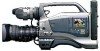
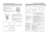
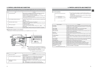
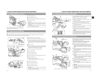
2. CONTROLS, INDICATORS AND CONNECTORS 2-6 Indications on the LCD Monitor and in the Viewfinder (Cont'd) ■ Auto White Balance Indication (Camera mode only) The AUTO WHITE indication and the result of the operation are displayed during the auto white balance adjustment operation. ☞ See "Auto White Balance Adjustment" on page 48. AUTO WHITE A OPERATION ■ Safety Zone Indication (Camera mode only) The indication of the following safety zone and center mark indications can be turned ON/OFF with the SAFETY ZONE item and CENTER MARK item on the LCD/VF (1/2) menu screen. ☞ See page 73. SAFETY ZONE CENTER MARK OFF OFF NORMAL OFF NORMAL ON 16 : 9 OFF 16 : 9 ON MEMO: When the ASPECT RATIO item on the CAMERA OPERATION menu screen is set to LETTER, 16:9 is indicated even if the SAFETY ZONE item is set to NORMAL. ■ Menu Setting Screen --- MENU --- CAMERA OPERATION.. CAMERA PROCESS AUDIO/VIDEO.. LCD/VF.. TC/UB/CLOCK.. OTHERS.. FILE MANAGE.. MENU ALL RESET CANCEL EXIT TOP MENU screen (Camera mode) Screen used for making various settings. The Menu Setting Screen appears when the STATUS button is pressed for 1 second or more. ☞ See "Setting Menu Screens" on page 66. 26 2. CONTROLS, INDICATORS AND CONNECTORS 2-7 Lens (Optional) [S14 x 7.3B12] ew q RET M A W T r !0 t y ui o !4 MACRO 1 FOCUS ring Manual focus ring. !1 !2 !3 2 ZOOM lever/ring This is the manual zoom ring equipped with a zoom lever. To adjust the zoom manually, turn the zoom mode knob @ to position "M". 3 IRIS ring Manual iris ring. To activate the auto iris feature, set the Iris Mode switch 7 to "A". 4 [VTR] Trigger button To start/stop shooting. 5 [RET] return video button The return video signal from the VTR section can be monitored in the viewfinder only while this button is pushed. * The playback picture can be viewed in the viewfinder during this operation. 6 ZOOM servo control lever To operate the servo zoom feature with this lever, set the ZOOM knob @ to "S". ● Pressing the "W" section of this lever increases the angle of the lens for a wider shooting angle. ● Pressing the "T" section of this lever narrows the lens angle perspective for telephoto shots. ● Pushing harder changes the speed of the zoom. 7 IRIS mode switch A : Activates the auto iris feature. M : Allows manual iris control. 8 Momentary auto iris button When the IRIS MODE switch 7 is at "M", pushing this button activates the Auto Iris Function while it is held down only. 9 [S] IRIS speed adjusting control For adjusting the iris operation speed. MEMO: If the speed becomes too fast, hunting may occur. To avoid the phenomena described above, perform adjustment again. 0 FILTER thread Protect the lens with a clear filter or UV filter by screwing the filter onto the thread inside the lens hood from the front. Other filters can be used for various effects. CAUTION: The filter thread section rotates, so pay attention when mounting a polarizing filter. ! ZOOM servo connector Connect an optional zoom servo unit here. @ ZOOM mode knob S : Servo zoom mode. Allows operation by the zoom servo control lever 6. M : Manual zoom mode. Allows zoom control by the zoom lever/ring 2. # BACK FOCUS ring/fixing screw For back focus adjustment only. Secure with the screw knob after adjustment. ☞ See "Back Focus Adjustment" on page 47. $ Macro focusing ring (for close-up shooting) By rotating this ring in the direction of the arrow, close-up shooting of very small objects becomes possible. Normal focus adjustment and zooming are not available in the macro mode. To shoot images in the macro mode, set the focus ring 1 to the infinite position (∞) and the zoom ring 2 to the maximum wide-angle position. To adjust the focus of the macro image, rotate this ring in the direction of the arrow until the object is focused. CAUTION: ● The back-focus knob is located close to the macro ring, be careful not to mistake the back-focus knob for the macro ring. ● After the required operation, be sure to return the macro focusing ring to the normal position. ☞ See "Attaching the Zoom Lens" on page 30. ☞ See "Back Focus Adjustment" on page 47. 27
-
 1
1 -
2
-
3
-
4
-
5
-
6
-
7
-
8
-
9
-
 10
10 -
 11
11 -
 12
12 -
 13
13 -
 14
14 -
 15
15 -
 16
16 -
 17
17 -
 18
18 -
 19
19 -
 20
20 -
21
-
22
-
23
-
24
-
25
-
26
-
27
-
28
-
29
-
30
-
31
-
32
-
33
-
34
-
35
-
36
-
37
-
38
-
39
-
40
-
41
-
42
-
43
-
44
-
45
-
46
-
47
-
48
-
49
 |
 |