Kyocera ECOSYS FS-1135MFP FS-1135MFP Fax Operation Guide - Page 18
Machine
 |
View all Kyocera ECOSYS FS-1135MFP manuals
Add to My Manuals
Save this manual to your list of manuals |
Page 18 highlights
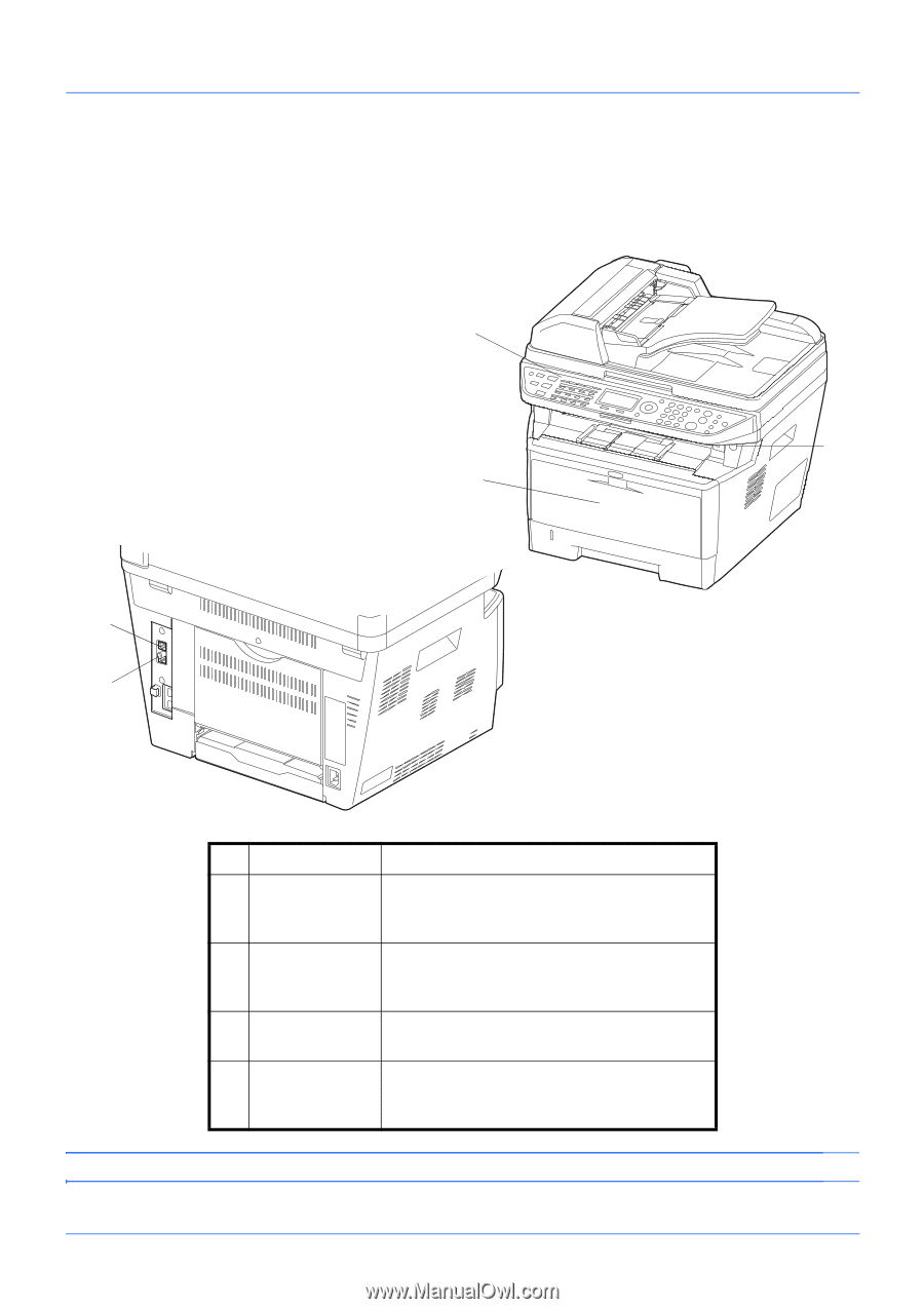
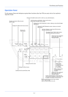
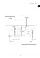
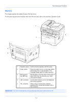
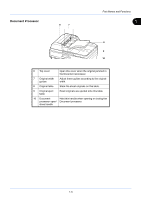
Part Names and Functions Machine This chapter explains the names of parts of the fax device. For the parts required when functions other than FAX are used, refer to the machine's Operation Guide. 1 2 3 4 5 1 Operation panel Perform the fax operation with this panel. 2 Power switch Press this switch to turn on the power before performing a fax or copy operation. The message display lights to enable operation. 3 Multi purpose tray (MP tray) Set the paper in this tray when using a type of paper other than the cassette (e.g., when using special paper). 4 LINE connector Connect the modular cord for the telephone line to this connector. 5 TEL connector When using a commercially available telephone set, connect the modular cord to this connector. IMPORTANT: You cannot automatically receive a fax when the power switch is turned off. 1-4
-
 1
1 -
2
-
3
-
4
-
5
-
6
-
7
-
8
-
9
-
10
-
11
-
12
-
 13
13 -
 14
14 -
 15
15 -
 16
16 -
 17
17 -
 18
18 -
 19
19 -
 20
20 -
 21
21 -
 22
22 -
 23
23 -
24
-
25
-
26
-
27
-
28
-
29
-
30
-
31
-
32
-
33
-
34
-
35
-
36
-
37
-
38
-
39
-
40
-
41
-
42
-
43
-
44
-
45
-
46
-
47
-
48
-
49
-
50
-
51
-
52
-
53
-
54
-
55
-
56
-
57
-
58
-
59
-
60
-
61
-
62
-
63
-
64
-
65
-
66
-
67
-
68
-
69
-
70
-
71
-
72
-
73
-
74
-
75
-
76
-
77
-
78
-
79
-
80
-
81
-
82
-
83
-
84
-
85
-
86
-
87
-
88
-
89
-
90
-
91
-
92
-
93
-
94
-
95
-
96
-
97
-
98
-
99
-
100
-
101
-
102
-
103
-
104
-
105
-
106
-
107
-
108
-
109
-
110
-
111
-
112
-
113
-
114
-
115
-
116
-
117
-
118
-
119
-
120
-
121
-
122
-
123
-
124
-
125
-
126
-
127
-
128
-
129
-
130
-
131
-
132
-
133
-
134
-
135
-
136
-
137
-
138
-
139
-
140
-
141
-
142
-
143
-
144
-
145
-
146
-
147
-
148
-
149
-
150
-
151
-
152
-
153
-
154
-
155
-
156
-
157
-
158
-
159
-
160
-
161
-
162
-
163
-
164
-
165
-
166
-
167
-
168
-
169
-
170
-
171
-
172
-
173
-
174
-
175
-
176
-
177
-
178
-
179
-
180
 |
 |