LG L26W58HA Operation Guide - Page 14
Conne, a pillow, speaker to the, LCDW/Monitor. - remote
 |
View all LG L26W58HA manuals
Add to My Manuals
Save this manual to your list of manuals |
Page 14 highlights
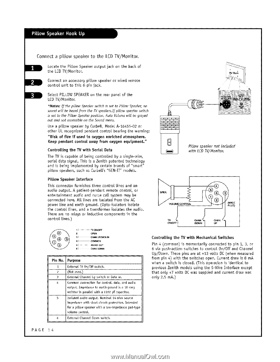
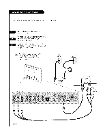
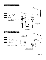
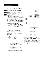
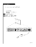
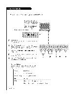
Conne_ a pillow speaker to the LCD W/Monitor. Locate the PiEow Speaker output jack on the back of the LCDTV/Nonitor, Connect an accessory piLLowspeaker or wired remote centre[ unit to this 6-pin jack. Select PILLOWSPEAKERon the rear pane[ of the LCDTViNonitor. *Rotes: If the pillow Speaker switch is set to Pillow Speaker_ no sound witl be h,e_rdflora the TVspeoker_If piltow speakerswitch is set to the Pillow Speakerposition, Auto Volumewfif be grQved out end not acce,_sibleon the Soundmenu, _w Use a piLLowspeaker by Curbe[[, Node[ Ao16455o02 or other UL recognized pendant control bearing the warning: "Risk of fire if used in oxygen enriched atmosphere. Keep pendant centre[ away from oxygen equipment." ControUing the W _th Seda| Data The TV is capable of being centre[ted by a singLe-wire, serial data signat. This is a Zenith patented technology and is being imptemented by certain brands of "smart" piLLowspeakers, such as Curbet['s "GEN41" models. Piltow Speaker Interface This connector furnishes three control Lines and an audio output. A patient-pendant remote control or entertainment audio and nurse ca[[ system may be connected here. At[ tines are isolated from the AC power Line and earth ground. (Opto-isoLato[s isolate the centre[ Lines, and a transformer isolates the audio. There are no relays or inductive components in the con[rot Unes.) Pillow speaker not included with LCD TV/f4onitor. 2 OPEN 3 CP_ANUPK)ATAiN 4 C...O...M..._...N......... t TA...VU..._0..F[.O....OUT e CHAUDOWN Pin No. Purpose 1 ExterPa[ l'V On/Off switch. 2 (Not used.) 3 Exterra[ Charmer Up switch or Data in. 4 Common cormectioo for control da_, nod audio output, Impedance to earth ground is a IO-meg resistor in parattet with a ilO0 pf capacitor, 5 IsoLated audio output. Nominal 14ohm source impedance with short circuit protection, intended for a piLLow speaker with a [ow-impedance pad-type votume controL 6 External Charmer Down switch, PAGE t4 ControUing the W with Mechanicat Switches Pin 4 (common) is momentarily connected to pin i, 3, or 6 via push-action switches to centre{ On/Of# and Channel Up/Dowm These pins are at +13 volts DC(when measured from pin 4) with the switches open. Current draw is 8 mA when a switch is c[osed. (This operation is identica[ to previous Zenith models using the 5-Wire Interface except that only +7 volts DC was supplied and current draw was only 2.5 mA.)
-
 1
1 -
2
-
3
-
4
-
5
-
6
-
7
-
8
-
 9
9 -
 10
10 -
 11
11 -
 12
12 -
 13
13 -
 14
14 -
 15
15 -
 16
16 -
 17
17 -
 18
18 -
 19
19 -
20
-
21
-
22
-
23
-
24
-
25
-
26
-
27
-
28
-
29
-
30
-
31
-
32
-
33
-
34
-
35
-
36
-
37
-
38
-
39
-
40
-
41
-
42
-
43
-
44
-
45
-
46
-
47
-
48
-
49
-
50
-
51
-
52
-
53
-
54
-
55
-
56
-
57
-
58
-
59
-
60
-
61
-
62
-
63
-
64
 |
 |