Pioneer 79AVi Owner's Manual - Page 14
Connecting up
 |
UPC - 012562768335
View all Pioneer 79AVi manuals
Add to My Manuals
Save this manual to your list of manuals |
Page 14 highlights
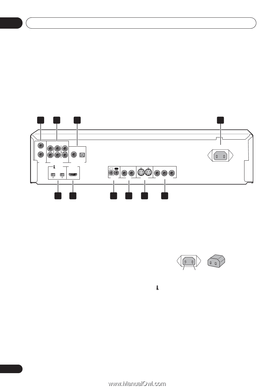
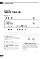
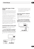
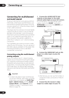
02 Connecting up Chapter 2 Connecting up Rear panel 12 3 4 FRONT SURROUND CENTER L L R AUDIO OUT (2ch) R SUB WOOFER AUDIO OUT (5.1ch) COAXIAL OPTICAL DIGITAL AUDIO OUT (AUDIO) HDMI OUT S400 IN OUT 1 2 CONTROL VIDEO OUT 1 2 Y PB PR S-VIDEO OUT COMPONENT VIDEO OUT AC IN 56 78 9 10 When connecting this player up to your TV, AV receiver or other components, make sure that all components are switched off and unplugged. 1 AUDIO OUT (2ch) Two channel analog audio outputs for connection to your TV, AV receiver or stereo system (page 16,19). 2 AUDIO OUT (5.1ch) Multichannel analog audio outputs for connection to an AV receiver with multichannel inputs (page 18). 3 DIGITAL AUDIO OUT - OPTICAL / COAXIAL Digital audio outputs for connection to a PCM, Dolby Digital, DTS and/or MPEGcompatible AV receiver (page 19). 4 AC IN Connect the supplied power cord here, then plug into a power outlet. Refer to the illustration below when doing so to make sure the neutral and live blades are lined up properly. AC IN Power cord NL LIVE NEUTRAL N : Neutral L : Live 5 (AUDIO) - i.LINK connectors 4-pin, S400 i.LINK connectors for connection to i.LINK-equipped receivers and other components. Each i.LINK connector acts simultaneously as both input and output (page 20). 6 HDMI OUT HDMI output providing a high quality interface for digital audio and video (page 22). 14 En
-
 1
1 -
2
-
3
-
4
-
5
-
6
-
7
-
8
-
 9
9 -
 10
10 -
 11
11 -
 12
12 -
 13
13 -
 14
14 -
 15
15 -
 16
16 -
 17
17 -
 18
18 -
 19
19 -
20
-
21
-
22
-
23
-
24
-
25
-
26
-
27
-
28
-
29
-
30
-
31
-
32
-
33
-
34
-
35
-
36
-
37
-
38
-
39
-
40
-
41
-
42
-
43
-
44
-
45
-
46
-
47
-
48
-
49
-
50
-
51
-
52
-
53
-
54
-
55
-
56
-
57
-
58
-
59
-
60
-
61
-
62
-
63
-
64
-
65
-
66
-
67
-
68
-
69
-
70
-
71
-
72
-
73
-
74
-
75
-
76
-
77
-
78
-
79
-
80
-
81
-
82
-
83
-
84
-
85
-
86
-
87
-
88
-
89
-
90
-
91
-
92
-
93
-
94
-
95
-
96
-
97
-
98
-
99
 |
 |